Pneumatic filing machine

A file and pneumatic technology, applied in filing/filing device, filing/filing device, metal processing equipment, etc., can solve the problems of low efficiency, easy arm soreness and fatigue, and frozen shoulder of workers, etc. Achieve the effect of improving work efficiency and reducing labor intensity

Inactive Publication Date: 2018-08-03
FUZHOU YOULI MACHINERY
View PDF5 Cites 1 Cited by
  • Summary
  • Abstract
  • Description
  • Claims
  • Application Information

AI Technical Summary

Problems solved by technology

[0002] Existing files all use manpower to file workpieces, the efficiency of workers is low when using them, and after a period of use, workers are prone to arm pain and fatigue, further reducing efficiency, and easily causing occupational diseases such as frozen shoulder

Method used


Image

  • Pneumatic filing machine
  • Pneumatic filing machine
  • Pneumatic filing machine

Examples


Embodiment Construction

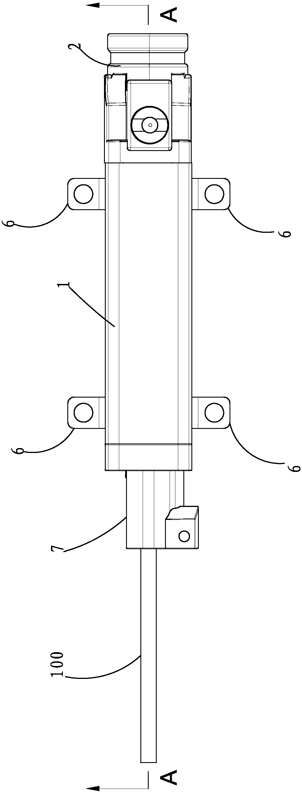
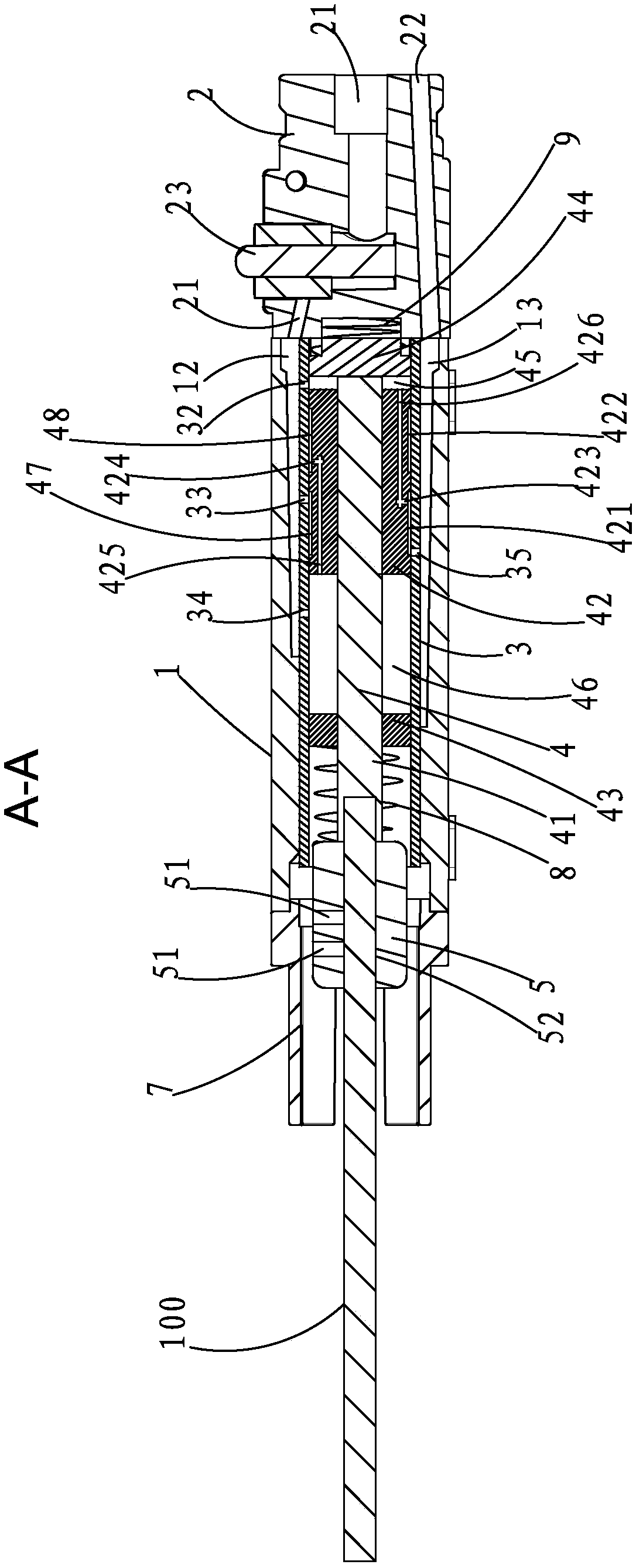
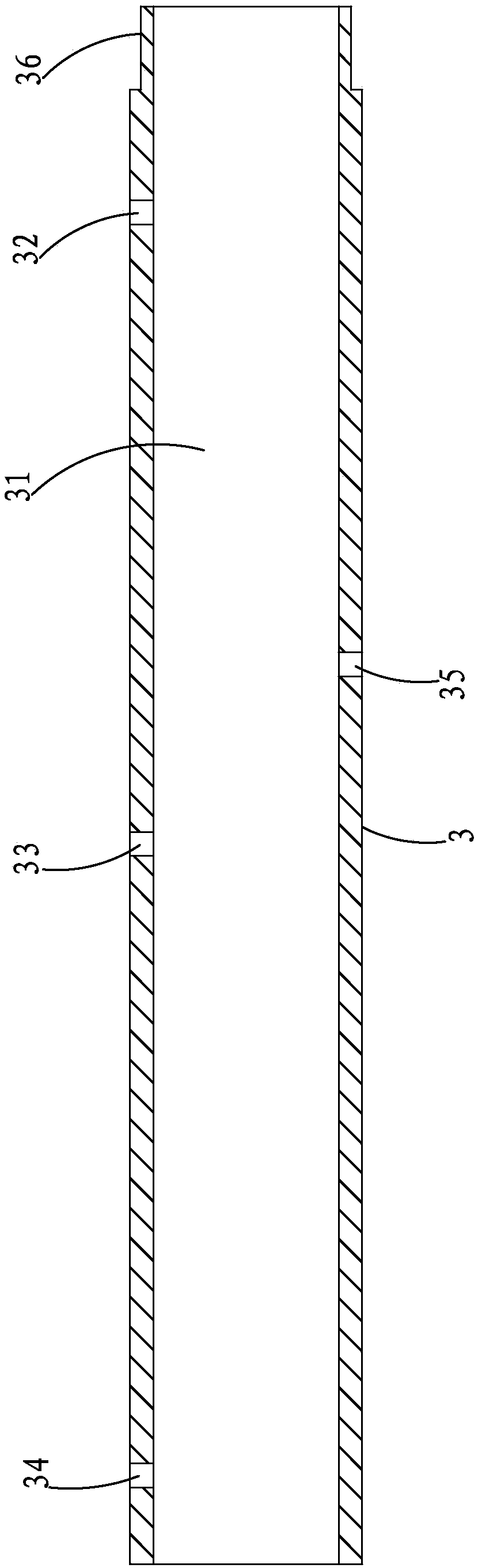
[0026] see Figure 1-7 As shown, a pneumatic file machine of the present invention also includes a main body 1, a valve body 2, a cylinder 3 and a piston rod group 4;

[0027] The piston rod group 4 includes a piston rod 41, a piston 42, a first piston cover 43 and a second piston cover 44; the piston 42 is airtightly slidable on the piston rod 41 left and right; The first piston cover 43 and the second piston cover 44 are fixedly connected to the two ends of the piston rod 41 one by one; the outer surface of the piston 42 is symmetrically provided with a first annular groove 421 and a second annular groove 422, the first A first counterbore 423 is provided at the bottom of an annular groove 421; a second counterbore 424 is provided at the bottom of the second annular groove 422, and a third counterbore 424 is provided on the outer wall of the piston 42 axially from the left end surface of the piston 42. A counterbore 425, a fourth counterbore 426 is opened axially from the r...


PUM


Abstract

The invention provides a pneumatic filing machine. The machine is characterized in that a piston rod set leftwards and rightwards reciprocate by a pneumatic technology; a file is mounted at the end part of a first piston cover; an air source is connected, and then an air valve is pressed, and the file can leftwards and rightwards reciprocate. With the adoption of the machine, the working efficiency is improved, and meanwhile, the working intensity of workers is reduced; and the machine is humanized.

Description

technical field [0001] The invention relates to the field of pneumatic technology, in particular to a pneumatic filing machine. Background technique [0002] Existing files all use manpower to file workpieces, and the efficiency of workers is low when they are used, and after a period of use, workers are prone to arm pain and fatigue, further reducing efficiency, and easily causing occupational diseases such as frozen shoulder. Contents of the invention [0003] The technical problem to be solved by the present invention is to provide a pneumatic file machine, which is driven pneumatically to realize the linear reciprocating movement of the piston rod group, and the automatic movement of the file can be realized after the file is fixedly connected to the piston rod group to improve efficiency. At the same time, it reduces the labor intensity of workers and is more humane. [0004] The present invention is realized as follows: a pneumatic file machine, which also includes ...

Claims


Application Information

Patent Timeline
Patent Type & Authority Applications(China)
IPC IPC(8): B23D67/02
CPCB23D67/02
Inventor 李发平
Owner FUZHOU YOULI MACHINERY
Why Eureka
Try Eureka