Spring-loaded thrust meter

A spring dynamometer, symmetrical technology, applied in the field of teaching experimental appliances

Inactive Publication Date: 2018-08-03
樊睿华
View PDF7 Cites 0 Cited by
  • Summary
  • Abstract
  • Description
  • Claims
  • Application Information

AI Technical Summary

Problems solved by technology

[0003] The technical problem to be solved by the present invention is to provide a spring dynamometer in view of the above-mentioned technical deficiencies. The center line positions on both sides of the main support frame are symmetrically arranged with the first chute with respect to the length direction. The second chute structure is arranged at the bottom, which solves the connection problem between the auxiliary support frame and the auxiliary support frame and the main support frame respectively; the first circular card slot is provided with the first spring, and the first spring is directly above the first spring. The first convex button, the second spring is arranged in the second circular card slot, and the second convex button structure is arranged directly above the second spring, which solves the problem of fixing the auxiliary support frame and the auxiliary support frame after storage; the auxiliary support frame is adopted Triangular blocks are symmetrically arranged on both sides of the center line in the thickness direction on the outside of one end, and triangular card slot structures are arranged symmetrically on both sides of the rectangular through hole, which solves the problem of fixing and supporting between the auxiliary support frame and the auxiliary support frame; one end of the auxiliary support frame is used There is a U-shaped fixed block at the center of the outside, and a first threaded hole structure is set at the center of the U-shaped fixed block, which solves the problem of fixing between the spring dynamometer and the auxiliary support frame

Method used


Image

  • Spring-loaded thrust meter
  • Spring-loaded thrust meter
  • Spring-loaded thrust meter

Examples


specific Embodiment approach 1

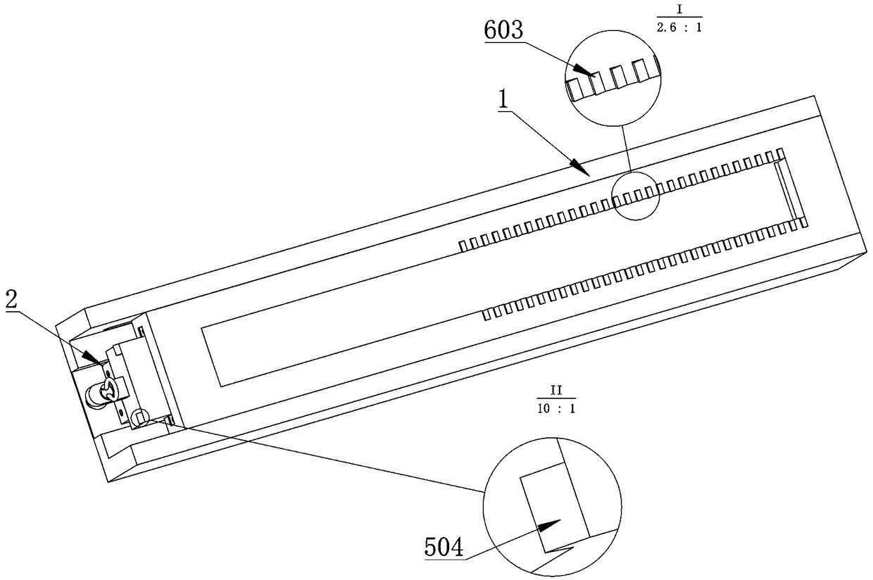
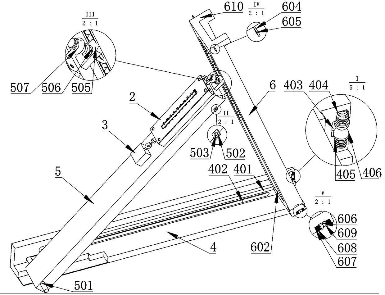
[0017] Specific implementation mode one: combine Figure 1-2As shown, it includes a support platform 1, a spring dynamometer 2 and a weight 3; the support platform 1 includes a main support frame 4, a secondary support frame 5 and an auxiliary support frame 6; the centerline positions on both sides of the main support frame 4 are symmetrical about the length direction A first chute (401) is provided; a second chute 402 is provided directly below the first chute (401); a first rectangular groove 403 is arranged symmetrically with respect to the length direction at one end of the main support frame 4; the first rectangular groove A first circular card slot 404 is arranged symmetrically on the upper and lower sides inside the slot 403; a first spring 405 is arranged in the first circular card slot 404; a first convex button 406 is arranged directly above the first spring 405; the auxiliary support frame 5 The first clamping shaft 501 is arranged symmetrically on both sides of the...


PUM


Abstract

The invention relates to the technical field of teaching experiment tools and especially relates to a spring-loaded thrust meter. A first slide chute is arranged symmetrically about the length direction at positions of center lines on two sides in the inner part of a main support rack. A second slide chute structure is arranged exactly below the first slide chute. Therefore, a problem of connection between a secondary support rack and the main support rack and between an auxiliary support rack and the main support rack is solved. A first spring is arranged in a first round clamp groove. A first salient button is arranged exactly above the first spring. A second spring is arranged in a second round clamp groove. A second salient button is arranged exactly above the second spring. Therefore,a problem of fixation of the secondary support rack and the auxiliary support rack in storage is solved. Triangular clamp blocks are symmetrically arranged about a middle line in the thickness direction on the outer part of one end of the secondary support rack. Triangular clamp chutes are arranged symmetrically on two sides of a rectangular through hole. Therefore, problems of fixation and supporting between the secondary support rack and the auxiliary support rack are solved.

Description

technical field [0001] The invention relates to the technical field of teaching and experiment appliances, in particular to a spring dynamometer. Background technique [0002] The spring dynamometer is a tool for measuring force. Its principle is as follows: First, any measurement is a process of comparing a certain physical quantity with a standard (that is, a unit). The measurement of force is to compare the effect of force with the known force. The process of comparing the effect; if the effect of a force is the same as the effect of 1 N force, the magnitude of this force is 1 N; secondly, the elongation of the spring is proportional to the magnitude of the force, and when determining the force of 1 N After the effect, it is easy to determine the effect of greater force and smaller force; in addition, the spring has good stability and can be used repeatedly; therefore, the force can be measured with a spring dynamometer. In the actual measurement, due to the certain resi...

Claims


Application Information

Patent Timeline
Patent Type & Authority Applications(China)
IPC IPC(8): G01L1/04G01L1/26G09B23/10
Inventor 樊睿华
Owner 樊睿华
Why Eureka
Try Eureka