An AODV Routing Method for Distributed Satellite Networks
A satellite network and distributed technology, applied in the field of satellite network communication, can solve problems such as waste of bandwidth resources, achieve full utilization and reduce impact
- Summary
- Abstract
- Description
- Claims
- Application Information
AI Technical Summary
Problems solved by technology
Method used
Image
Examples
example 1
[0047] set as Figure 5 The minimum available bandwidth of the path T1-CA1-CR1 in the shown satellite network topology is 2.2Mb / s and the minimum available bandwidth of the path T1-CA2-CR1 is 2.4Mb / s;
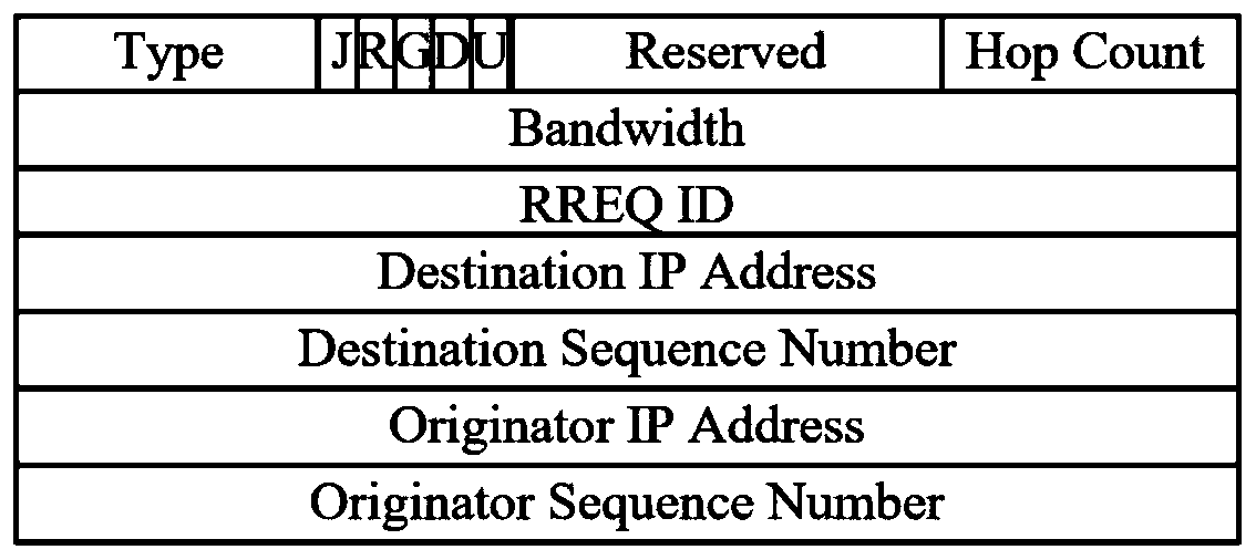
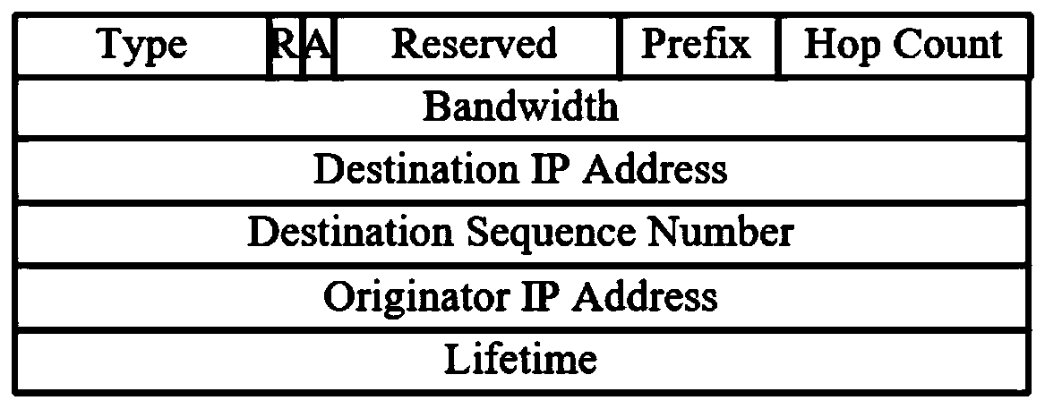
[0048] The source node broadcasts the RREQ message to the two paths. During the transfer process, the RREQ obtains the minimum available bandwidth of 2.2Mb / s and 2.4Mb / s respectively. When it reaches the destination node, an RREP message is generated and the minimum available bandwidth parameter is passed to RREP information;
[0049] The destination node returns the RREP message according to the reverse route formed. The source node first receives the minimum available bandwidth in the RREP message returned by the path T1-CA1-CR1 is greater than the minimum bandwidth required for sending, directly generates an effective routing table, and sends data.
example 2
[0051] set as Figure 5 The minimum available bandwidth of the path T1-CA1-CR1 in the shown satellite network topology is 1.8Mb / s and the minimum available bandwidth of the path T1-CA2-CR1 is 2.4Mb / s;
[0052] The source node broadcasts the RREQ message to the two paths. During the transfer process, the RREQ obtains the minimum available bandwidth of 1.8Mb / s and 2.4Mb / s respectively. When it reaches the destination node, an RREP message is generated and the minimum available bandwidth parameter is passed to RREP information;
[0053] The destination node returns the RREP message to the source node according to the reverse path of the RREP message generated by them. The source node first receives the RREP message returned by the path T1-CA1-CR1, and the minimum available bandwidth is 1.8Mb / s, which is less than The bandwidth required for the minimum transmission, generating an invalid routing table;
[0054] Within the time threshold, the source node receives the RREP message...
example 3
[0056] set as Figure 5 The minimum available bandwidth for the path T1-CA1-CR1 in the satellite network topology shown is 1.6Mb / s and the minimum available bandwidth for the path T1-CA2-CR1 is 1.8Mb / s;
[0057] The source node broadcasts the RREQ message to the two paths. During the transfer process, the RREQ obtains the minimum available bandwidth of 1.6Mb / s and 1.8Mb / s respectively. When it reaches the destination node, an RREP message is generated and the minimum available bandwidth parameter is passed to RREP information;
[0058] The destination node returns the RREP message to the source node according to the reverse path of the RREP message generated by them. The source node first receives the RREP message returned by the path T1-CA1-CR1, and the minimum available bandwidth is 1.6Mb / s, which is less than The bandwidth required for the minimum transmission, generating an invalid routing table;
[0059] Within the time threshold, the source node receives the RREP messa...
PUM
 Abstract
Description
Claims
Application Information
 - R&D
- Intellectual Property
- Life Sciences
- Materials
- Tech Scout
- Unparalleled Data Quality
- Higher Quality Content
- 60% Fewer Hallucinations
Browse by: Latest US Patents, China's latest patents, Technical Efficacy Thesaurus, Application Domain, Technology Topic, Popular Technical Reports.
© 2025 PatSnap. All rights reserved.Legal|Privacy policy|Modern Slavery Act Transparency Statement|Sitemap|About US| Contact US: help@patsnap.com


