Sewing machine punching device for producing shoes

A technology for sewing machines and shoes, applied in metal processing, etc., can solve problems such as inconsistent punching positions, check punching quality, and affect punching quality, so as to improve convenience and accuracy, reduce production costs, and ensure punching quality effect

Active Publication Date: 2018-08-07
江西源轮纺织有限公司
View PDF6 Cites 6 Cited by
  • Summary
  • Abstract
  • Description
  • Claims
  • Application Information

AI Technical Summary

Problems solved by technology

However, most of the existing punching devices are structural forms in which the cylinder drives the stamping block to punch, and the material can only be cut through the impact force for punching. On the one hand, the smoothness of the incision during punching cannot be guaranteed, which affects the quality of punching. On the one hand, the scraps cut by stamping tend to accumulate in the punching hole, which is inconvenient to take out and affect the next punching operation. In addition, the support plate supporting the sole is mostly fixed on the frame, which is inconvenient to adjust and rotate. It is impossible to check the quality of the punching holes during the stamping process, which will easily cause inconsistent punching positions and affect the appearance, which will bring a great burden to shoemaking and increase production costs

Method used


Image

  • Sewing machine punching device for producing shoes
  • Sewing machine punching device for producing shoes
  • Sewing machine punching device for producing shoes

Examples


Embodiment Construction

[0018] The following will clearly and completely describe the technical solutions in the embodiments of the present invention with reference to the accompanying drawings in the embodiments of the present invention. Obviously, the described embodiments are only some, not all, embodiments of the present invention. Based on the embodiments of the present invention, all other embodiments obtained by persons of ordinary skill in the art without making creative efforts belong to the protection scope of the present invention.

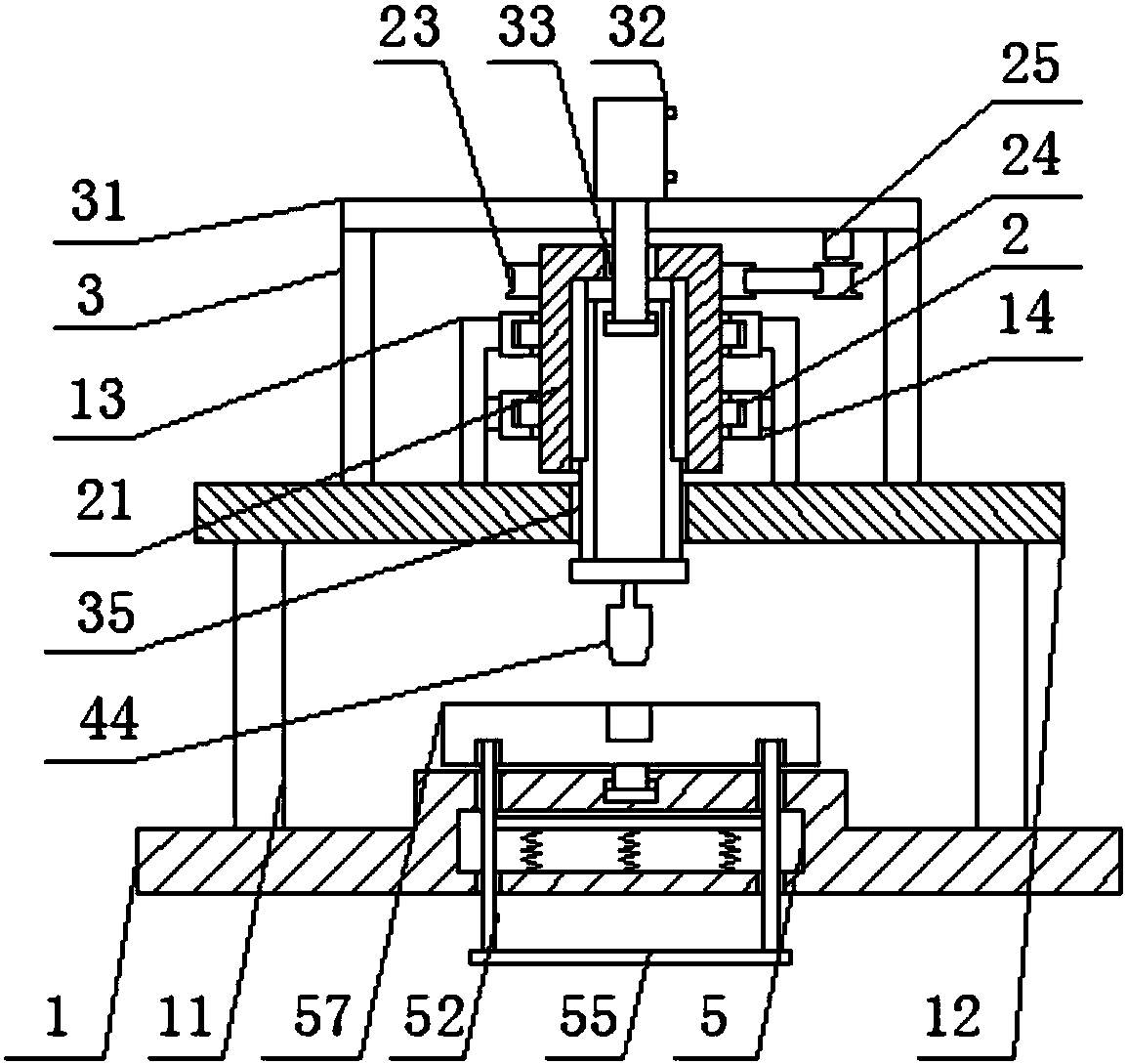
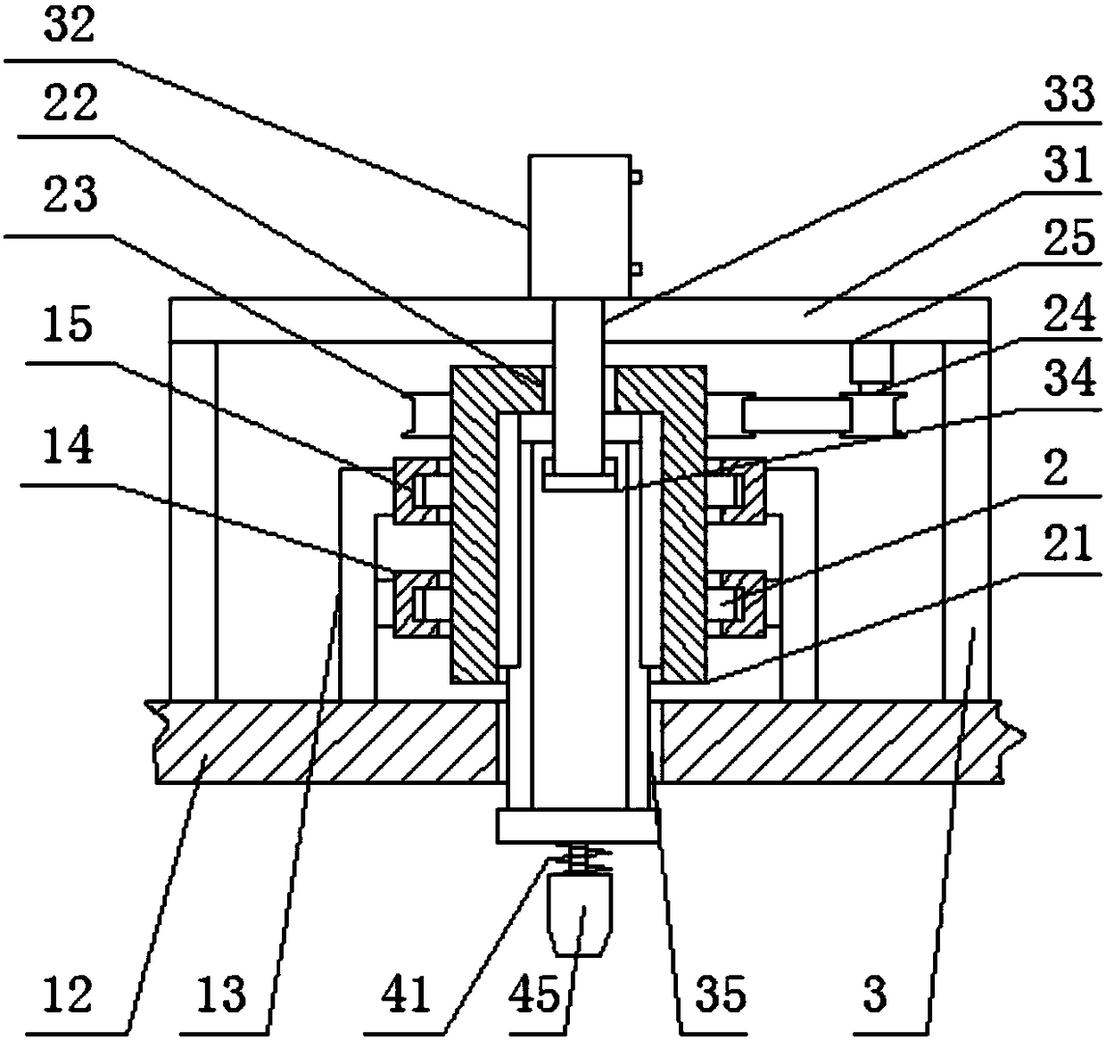
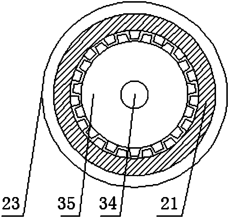
[0019] see Figure 1-5 , the present invention provides a technical solution: a sewing machine punching device for shoemaking, including a bottom plate 1, the two sides of the upper surface of the bottom plate 1 are fixedly connected with a first mounting plate 12 through a first support rod 11, the first mounting plate 1 The inner two ends of the upper surface of the plate 12 are fixedly connected with a positioning seat 14 through a support frame 13, and the...


PUM


Abstract

The invention discloses a sewing machine punching device for producing shoes. The sewing machine punching device comprises a bottom plate, first installation plates are fixedly connected to two sidesof the upper surfaces of the bottom plate through first supporting rods, locating seats are fixedly connected to two ends of the inner sides of the upper surfaces of the first installation plates through supporting frames, and annular holes are formed in the locating seats. A spline tube is rotatably connected into the annular holes through annular blocks, an avoidance hole is formed in the centerof the upper surface of the spline tube, a driven belt wheel is fixedly connected to the upper end of the outer surface of the spline tube, a second installation plate is fixedly connected to the outer side of the upper surface of the first installation plate through a second supporting rod, a motor is fixedly arranged on the rear side of the lower surface of the second installation plate throughbolts, and a driving belt wheel is fixedly connected to the lower surface of the motor through a shaft. The sewing machine punching device for producing the shoes can greatly improve the convenienceand accuracy of punching, guarantees the drilling quality and reduces the production cost.

Description

technical field [0001] The invention relates to the technical field of punching devices, in particular to a sewing machine punching device for shoemaking. Background technique [0002] In the shoemaking process, it is often necessary to drill holes on the sole to facilitate further installation and processing, which requires the use of a sewing machine's punching device. However, most of the existing punching devices are structural forms in which the cylinder drives the stamping block to punch, and the material can only be cut through the impact force for punching. On the one hand, the smoothness of the incision during punching cannot be guaranteed, which affects the quality of punching. On the one hand, the scraps cut by punching are easy to remain and accumulate inside the punching hole, which is inconvenient to take out and affect the next punching operation. In addition, the support plate supporting the sole is mostly fixed on the frame, which is inconvenient to adjust a...

Claims


Application Information

Patent Timeline
Patent Type & Authority Applications(China)
IPC IPC(8): B26F1/02B26F1/14B26D7/18
CPCB26D7/1818B26F1/02B26F1/14
Inventor 黄景长
Owner 江西源轮纺织有限公司
Why Eureka
Try Eureka