
Flow sensor

A flow sensor and fluid technology, applied in the field of flow sensors, can solve the problems of flow measurement influence, bubble inclusion, etc., and achieve the effect of improving accuracy

Pending Publication Date: 2018-08-07
SUZHOU IN SITU CHIP TECH CO LTD
View PDF0 Cites 6 Cited by
  • Summary
  • Abstract
  • Description
  • Claims
  • Application Information

AI Technical Summary

Problems solved by technology

However, air bubbles sometimes appear in the liquid, and if they adhere to the sensor, it will have a great impact on the flow measurement

Method used


Image

  • Flow sensor
  • Flow sensor

Examples


Embodiment Construction

[0039] Specific embodiments of the present invention will be described in detail below in conjunction with the accompanying drawings. It should be understood that the specific embodiments described here are only used to illustrate and explain the present invention, and are not intended to limit the present invention.

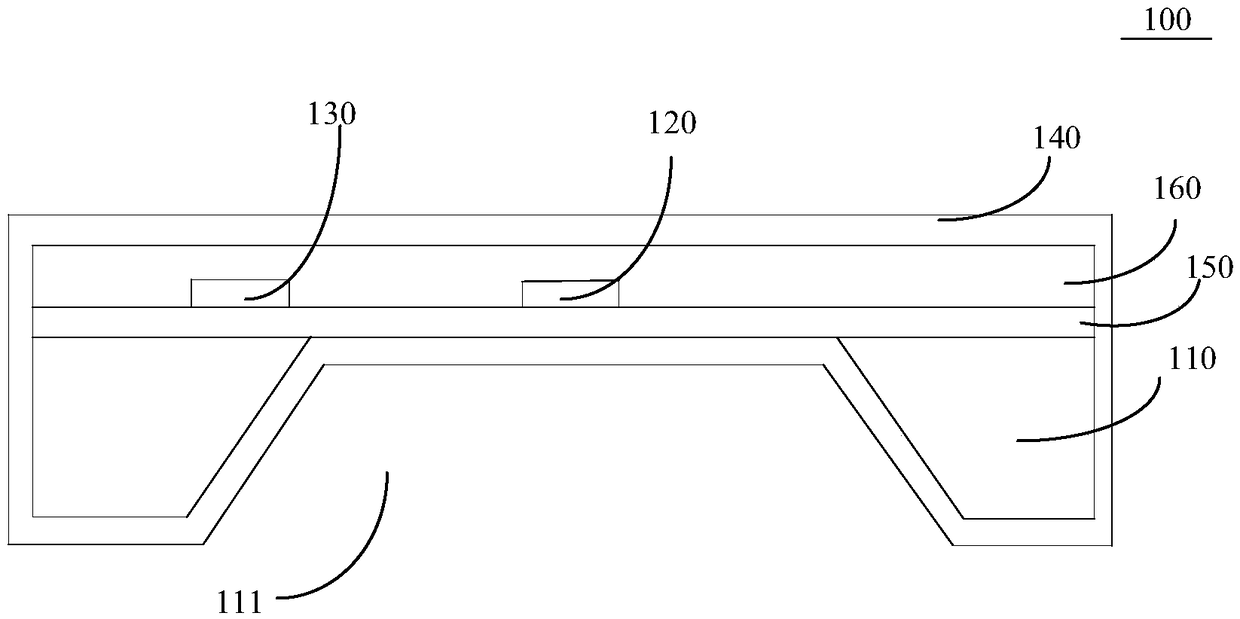
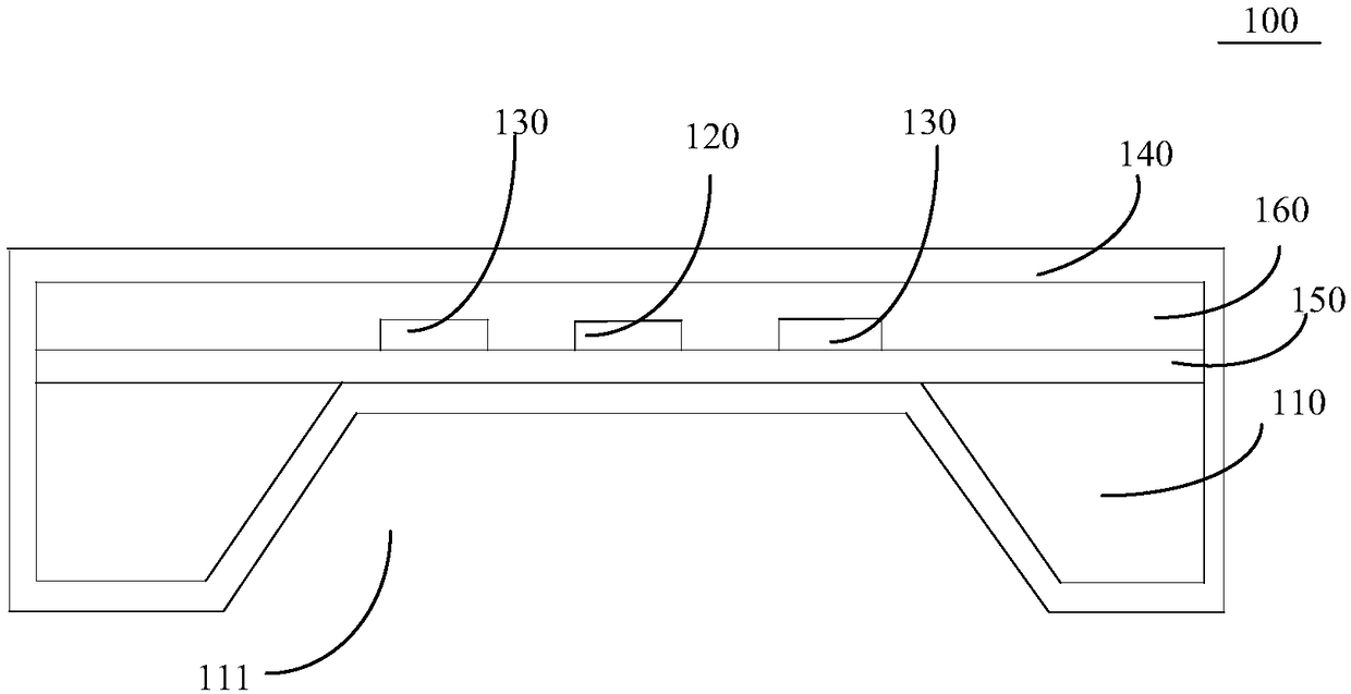
[0040] like figure 1 As shown, the present invention relates to a flow sensor 100 comprising a substrate 110 , a heating element 120 , at least one temperature sensing element 130 and a hydrophilic layer 140 . Wherein, both the heating element 120 and the temperature sensing element 130 are formed on the substrate 110 . Moreover, there is a predetermined interval between the temperature sensing element 130 and the heating element 120 , so as to obtain the flow rate of the fluid passing through the flow sensor 100 by measuring the temperature change of the temperature sensing element 130 or the heating element 120 . The hydrophilic layer 140 covers the entire o...


PUM


Abstract

The invention discloses a flow sensor. The flow sensor comprises a substrate; a heating element, formed on the substrate; at least one temperature-sensing element, wherein the temperature-sensing element is formed on the substrate, and a preset distance is formed between the temperature-sensing element and the heating element, so the flow of fluid flowing through the flow sensor is obtained by measuring the temperature change of the temperature-sensing element; and a hydrophillic layer, wherein the outer surface of the whole flow sensor is covered by the hydrophillic layer, so bubbles in the fluid are inhibited from being adhered to the outer surface of the flow sensor. The flow sensor disclosed by the invention is provided with the hydrophillic layer, the outer surface of the whole flow sensor is covered by the hydrophillic layer, and the installed hydrophillic layer has strong attraction to liquid in the fluid, so the bubbles in the fluid can be inhibited from being adhered to the surface of the flow sensor, the bubbles cannot affect the measurement of the flow sensor 100 to the flow velocity, and furthermore the accuracy of the flow sensor in measuring the flow of the fluid canbe improved.

Description

technical field [0001] The invention relates to the technical field of fluid measurement, in particular to a flow sensor. Background technique [0002] MEMS is an organic combination of microelectronics technology and mechanical engineering technology, specifically referring to high-tech devices on the scale of several millimeters or even microns. In the field of flow measurement, MEMS flow sensors are widely used in the field of small and micro flow, specifically measuring the flow of about 1uL / min to 1L / min. However, air bubbles sometimes appear in the liquid, and if they adhere to the sensor, it will have a great impact on the flow measurement. [0003] At present, most MEMS liquid flow sensors have no prevention of bubble adhesion, mainly because most of the measured pipe diameters are below 5mm, and the velocity of the liquid flow is relatively high. For example, the flow rate of 0.5L / min is under the pipe diameter of 5mm. According to the formula: flow = cross sectio...

Claims


Application Information

Patent Timeline
Patent Type & Authority Applications(China)
IPC IPC(8): G01F1/688
CPCG01F1/688
Inventor 温赛赛胡慧珊马硕王新亮
Owner SUZHOU IN SITU CHIP TECH CO LTD
Learn More