Lifting device for cable well and cable well

A technology of lifting device and cable well, which is applied in the direction of cable installation, cable installation, and cable installation device in the cable room, which can solve the problems of low work efficiency and achieve the effect of improving safety and preventing accidental falling

Pending Publication Date: 2018-08-07
GUANGDONG POWER GRID CO LTD +1
View PDF5 Cites 0 Cited by
  • Summary
  • Abstract
  • Description
  • Claims
  • Application Information

AI Technical Summary

Problems solved by technology

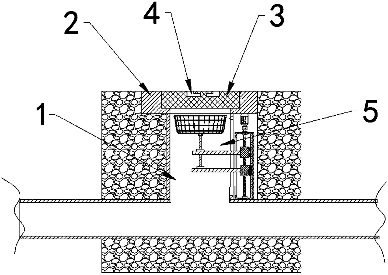
[0004] The purpose of the present invention is to provide a lifting device and a cable well for cable wells to solve the technical problem of low work efficiency when workers carry ladders into the cable well in the prior art

Method used


Image

  • Lifting device for cable well and cable well
  • Lifting device for cable well and cable well
  • Lifting device for cable well and cable well

Examples


Embodiment Construction

[0047] The technical solutions of the present invention will be clearly and completely described below in conjunction with the accompanying drawings. Apparently, the described embodiments are some of the embodiments of the present invention, but not all of them. Based on the embodiments of the present invention, all other embodiments obtained by persons of ordinary skill in the art without making creative efforts belong to the protection scope of the present invention.

[0048] In the description of the present invention, it should be noted that the terms "center", "upper", "lower", "left", "right", "vertical", "horizontal", "inner", "outer" etc. The indicated orientation or positional relationship is based on the orientation or positional relationship shown in the drawings, and is only for the convenience of describing the present invention and simplifying the description, rather than indicating or implying that the referred device or element must have a specific orientation, ...


PUM


Abstract

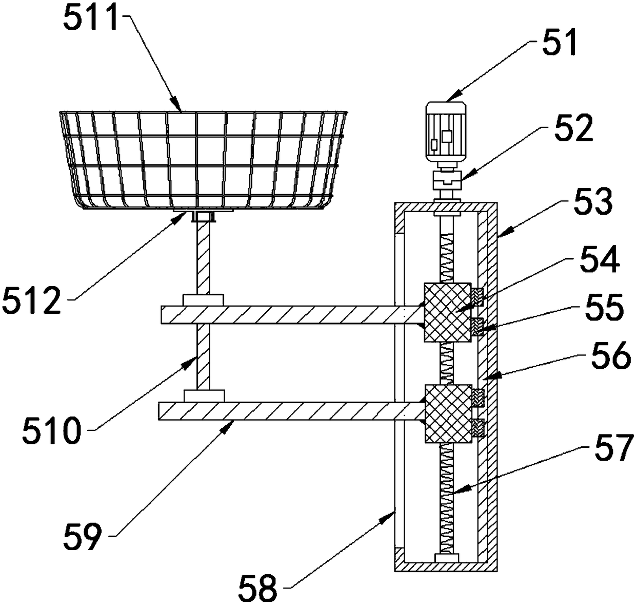
The invention provides a lifting device for a cable well and the cable well and relates to the technical field of electrical equipment. The lifting device comprises a lifting mechanism, a supporting mechanism and a protective structure, wherein the lifting mechanism is connected with the supporting mechanism and is used for driving the supporting mechanism to rise or fall; the protective structureis arranged on the supporting mechanism and is used for rising or falling along with the supporting mechanism. The lifting device and the cable well provided by the invention have the beneficial effects that in the technical scheme, the lifting mechanism is utilized for controlling rise or fall of the supporting mechanism, and by rise or fall of the supporting mechanism, the protective structureis driven to carry out actions of rising or falling in the cable well, therefore, a worker does not need to carry a ladder during construction in the cable well, and can be convenient and safe to riseor fall in the cable well only by controlling the lifting mechanism to carry out indirect lifting control on the protective structure, and the effect is very obvious especially in a deeper cable well.

Description

technical field [0001] The invention relates to the technical field of electric equipment, in particular to a lifting device for a cable well and the cable well. Background technique [0002] With the rapid development of the economy, the real estate industry has also developed rapidly. Generally, in residential quarters, more and more power equipment is deployed, and the most important part is the layout of cable wells, which are large in number and close to roads and residences. The location is also very conspicuous. [0003] At present, when the staff in the electric power industry need to go down into the cable shaft for laying-out operations, they generally need to use a ladder to go up and down, but for deeper cable shafts, workers need to carry a ladder at any time, which greatly affects the work. The work efficiency of personnel is not only troublesome to operate, but also easy to cause safety hazards. Contents of the invention [0004] The object of the present ...

Claims


Application Information

Patent Timeline
Patent Type & Authority Applications(China)
IPC IPC(8): H02G9/10H02G1/00B66F11/00
CPCH02G1/00H02G9/10B66F11/00
Inventor 沈瑞锡
Owner GUANGDONG POWER GRID CO LTD
Why Eureka
Try Eureka