
Voice coil motor with relatively high performance

A voice coil motor, the best technology, applied in the field of voice coil motors, can solve the problems of unable to adjust the far focus, difficult to enlarge the structure, long focusing time, etc., to achieve the effect of prolonging the standby time, improving characteristics, and fast focusing

Inactive Publication Date: 2018-08-07
SUZHOU FORCECON ELECTRIC
View PDF2 Cites 0 Cited by
  • Summary
  • Abstract
  • Description
  • Claims
  • Application Information

AI Technical Summary

Problems solved by technology

However, the existing voice coil motor can only move in one direction under the action of electromagnetic force, so it can only adjust close focus, but cannot adjust far focus, and the focusing time is longer
[0004] In addition, with the vigorous development of smart phones and other markets, the demand for voice coil motors is increasing, and customers have higher and higher requirements for the characteristics of voice coil motors. In order to meet the development of thinner and lighter products, existing voice coil motors It is difficult to make its structure larger, so improving the characteristics of the motor and increasing the magnetic force of the motor without increasing the size of the product has always been a problem for the industry to seek breakthroughs

Method used


Image

  • Voice coil motor with relatively high performance
  • Voice coil motor with relatively high performance
  • Voice coil motor with relatively high performance

Examples


Embodiment

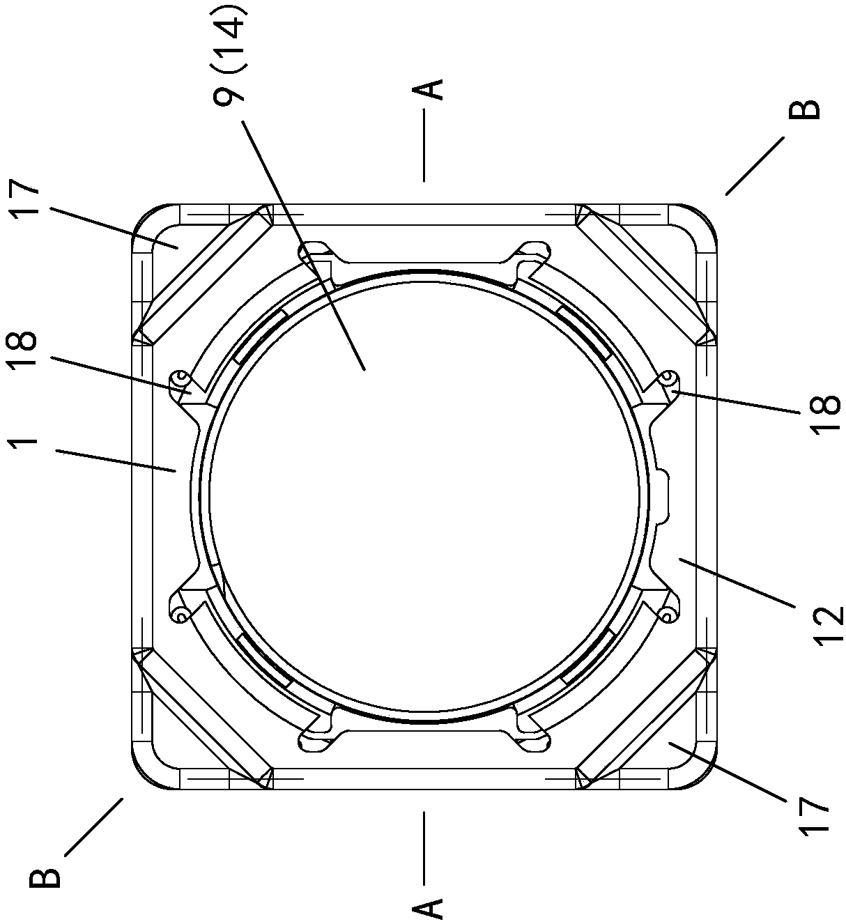
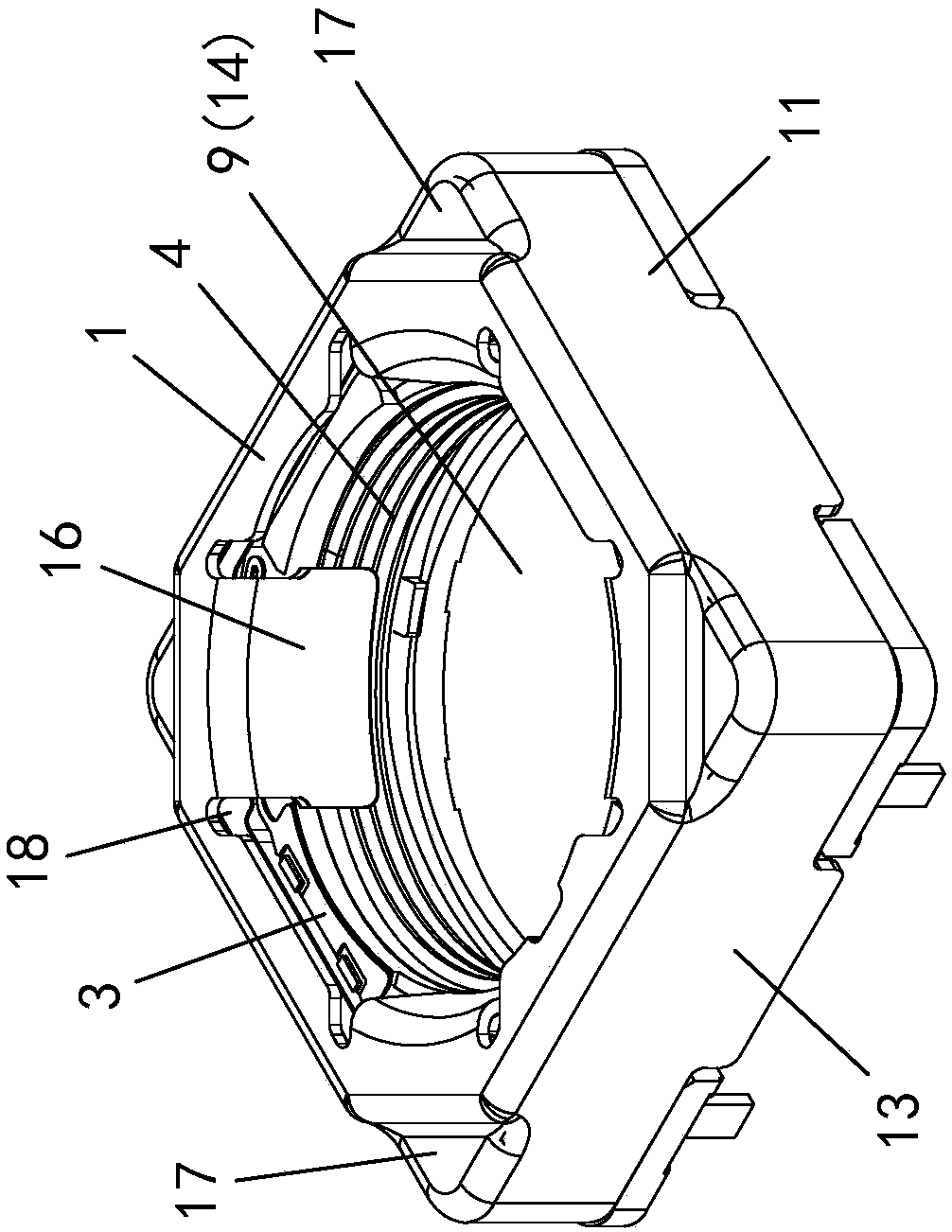
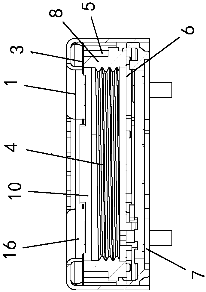
[0036] Example: see attached Figure 1~6 As shown, a voice coil motor with better performance is formed by assembling and positioning the first assembly body and the second assembly body in the up and down direction; through the combined assembly form of the two assemblies, the assembly efficiency of the voice coil motor can be improved and the Product yield.

[0037] The first assembly includes a yoke 1, a magnet 2 and an upper elastic piece 3; the magnet 2 is fixed inside the yoke 1 in the circumferential direction, and the first elastic end of the upper elastic piece 3 is positioned on the yoke Below the top cover of Iron 1;

[0038] The second assembly includes a carrier 4, a coil 5, a lower elastic piece 6 and a base 7; the carrier 4 includes a seat 8, and a first through hole 9 is opened in the seat 8 along the up and down direction for assembling the lens of the camera The upper end surface of the seat body 8 is adhesively connected to locate the second elastic end of...


PUM


Abstract

A voice coil with relatively high performance is obtained through vertical assembling and fixing of a first assembling member and a second assembling member. The first assembling member comprises a yoke, a magnet and an upper elastic plate. The second assembling member comprises a carrier, a coil, a lower elastic plate and a base. The seat of the carrier is provided with a first through hole. A second elastic end of the upper elastic plate is adhered and fixed to the upper end surface of the seat. A first elastic end of the lower elastic plate is adhered and fixed to the lower end surface of the seat. The second elastic end of the lower elastic plate is fixed to the upper part of the base. The coil winds the carrier. The coil and the magnet are correspondingly arranged. When the coil is not energized, the upper elastic plate and the lower elastic plate are horizontal planar members and no deformation occurs. The yoke comprises a cover-shaped body which is composed of a rectangular topplate and four side plates. The middle part of the rectangular top plate is provided with a second through hole. The four side plates are formed through integral extending of the rectangular top platealong the four sides and downwards bending. The middle part of the rectangular top plate is also provided with a plurality of folding parts. Each folding part is formed through integral extending ofthe rectangular top plate correspondingly with the second through hole and downwards bending.

Description

technical field [0001] The invention relates to a voice coil motor for a miniature camera, in particular to a voice coil motor with better performance. The miniature camera can be assembled and applied to thin electronic products such as mobile phones, tablet computers, and smart watches. Background technique [0002] In existing camera voice coil motor (VCM) designs, the structure typically includes a carrier positioned within the yoke of the motor. The carrier is provided with upper and lower first through holes for assembling the lens of the camera; wherein, the outer periphery of the base body is provided with a coil, and the yoke of the motor is provided with a magnet corresponding to the coil, so that when the coil is energized, the carrier The up and down direction displacement can be generated due to electromagnetic induction, so as to realize the zooming and focusing of the camera; the upper or / and lower end faces of the carrier are also positioned with shrapnel fo...

Claims


Application Information

Patent Timeline
IPC IPC(8): H02K33/18H02K33/02G03B13/34G02B7/04
CPCH02K33/18G02B7/04G03B13/34H02K33/02
Inventor 赖俊男
Owner SUZHOU FORCECON ELECTRIC
Learn More