
Electromagnetic drive and method of production thereof

Inactive Publication Date: 2016-03-10
CENT BADAN KOSMICZNYCH POLSKIEJ AKADI NAUK
View PDF3 Cites 4 Cited by
  • Summary
  • Abstract
  • Description
  • Claims
  • Application Information

AI Technical Summary

Benefits of technology

The patent proposes a solution for an electromagnetic drive that has insufficient energy. The invention proposes a multi-sectional drive with a core composed of at least two partially open sections. However, instead of increasing the number of turns and size of the core, the invention provides a solution using a separating element made of material with lower magnetic permeability. This solution allows for the partial closing of the core by the closing elements, which are located outside the core and connected to the core by a separating element. The winding runs in grooves on the core and the closing elements contain iron. The invention also provides a method of producing the electromagnetic drive with a partially open core and a moveable hammer made of closing and separating elements. The core is surrounded with a movable hammer, which is only partially closed in conditions of no current flow. The invention is effective in solving the problem of insufficient energy in electromagnetic drives.

Problems solved by technology

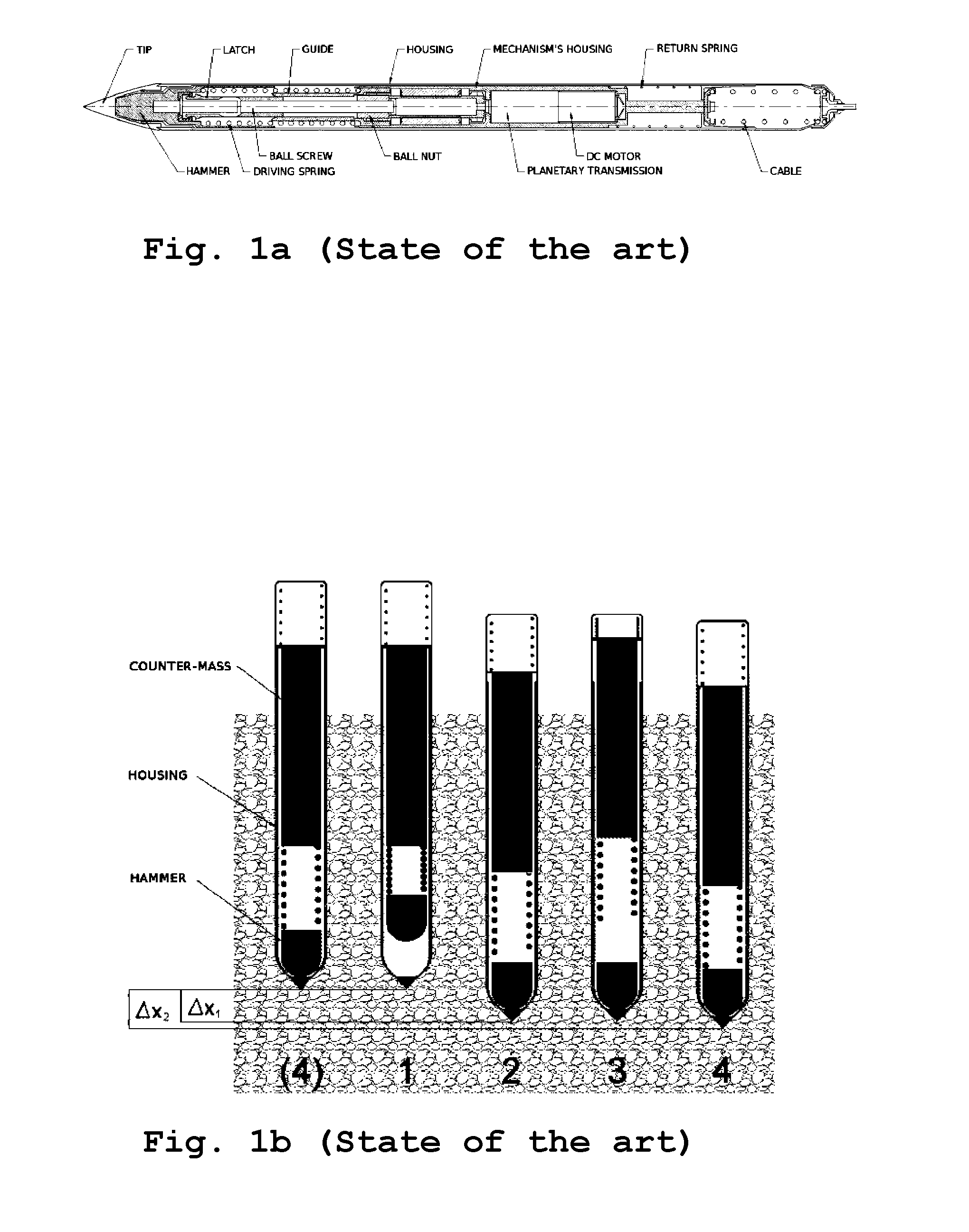
In the last phase 4 the counter-mass accelerated by the force of the return spring hits the housing, what results in an additional sinking.
In many cases permanent magnets are not allowed, because presence of a permanent magnet disturbs the readout of certain measurement devices.
Such electromagnetic device has a disadvantage of being prone to damages due in case of shock due to the changes in thickness of the exterior surface.
The shape and size of the penetrator make this task very difficult.
Such drive could not deliver sufficient amount of energy for effective hammering.

Method used


Image

  • Electromagnetic drive and method of production thereof
  • Electromagnetic drive and method of production thereof
  • Electromagnetic drive and method of production thereof

Examples


Embodiment Construction

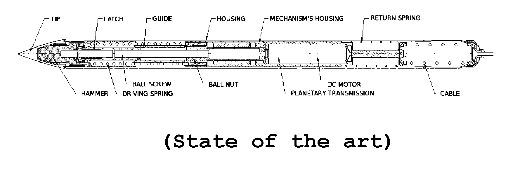
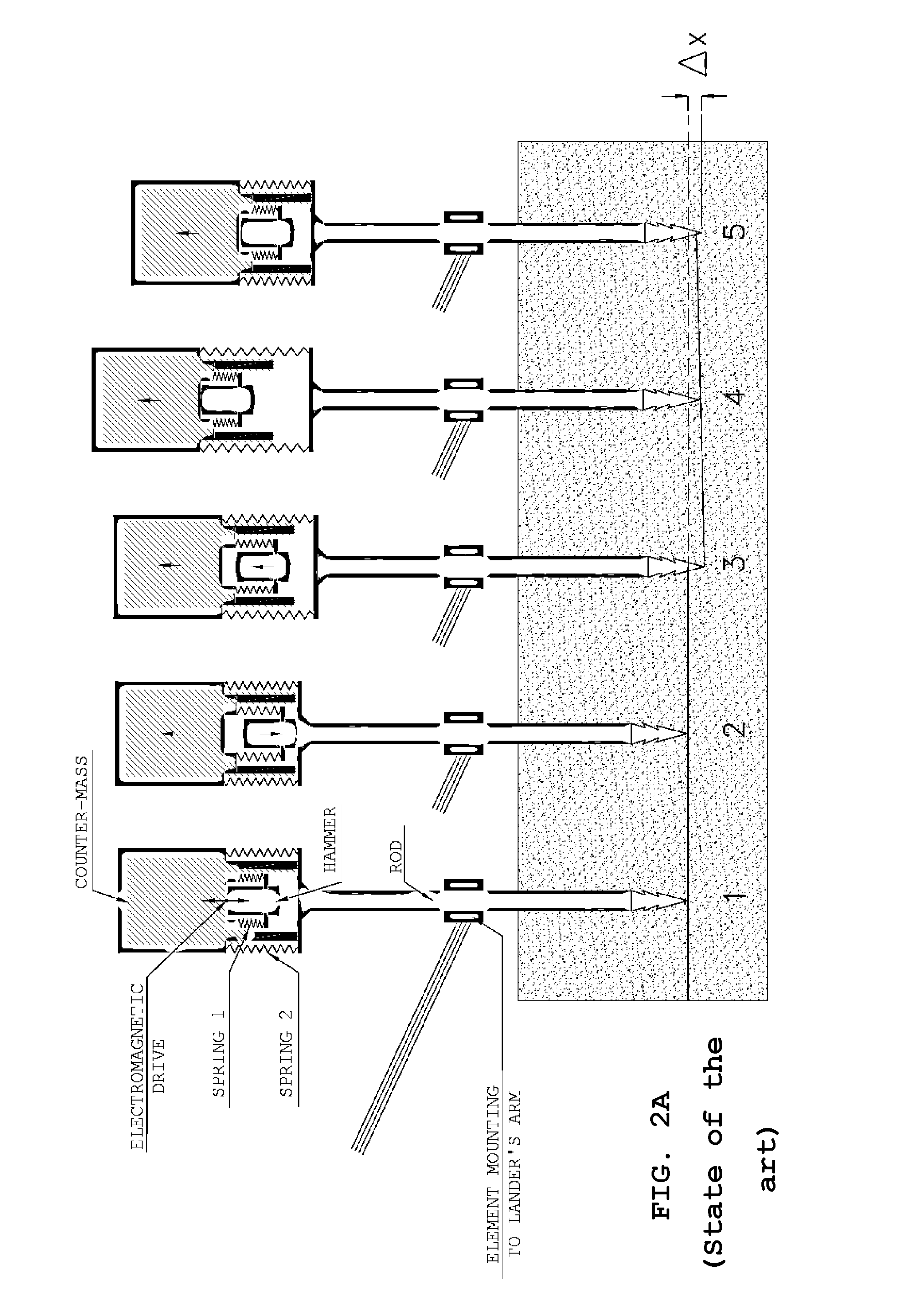
[0029]The penetrating capability of a self-driven hammering penetrator depends first of all on the energy of hitting by the hammer and cross-section of the hammered housing. The shape of the tip and the penetrator's length are also significant. Further there is described a penetrator with diameter of 25.4 mm, with the drive according to the invention. During the operational cycle of the self-driven hammered penetrator a part of energy is transferred in the direction of hammering, and a part in the opposite direction, disadvantageous for the operation, according to the conservation of momentum law. A significant parameter influencing a high efficiency of energy transfer in the hammering direction are proportions of three masses: of the penetrator's housing, of the hammer and of the counter-mass. The mass of the hammer should be relatively small in comparison with the mass of the counter-mass to gain the most energy during acceleration. On the other hand, the mass of the hitting hamme...


PUM

PropertyMeasurementUnit
Lengthaaaaaaaaaa
Currentaaaaaaaaaa
Energyaaaaaaaaaa

Abstract

The object of the invention is an electromagnetic drive comprising a core composed of at least two partially open sections. Each section partially surrounds the winding and is being closed by a closing element moveably connected to the core. This element is arranged so that in conditions of no current flow through the winding the core is partially not closed. The closing elements are arranged outside of the core and the winding and are connected to each other by a separating element made of material having lower magnetic permeability. The object of the invention is also a winding core composed of at least two partially open sections arranged along the axis of the core, characterized in that the openings of the core's sections are located in its substantially outer portion. Preferably, the core has axial symmetry and is equipped with a groove between sections adapted to accommodate the wire connecting the windings. Preferably, the separation of adjacent sections of the core corresponds to the length of a section. Furthermore, the object of the invention is a method of producing of electromagnetic drive comprising a partially open core, a winding and a moveable portion of the core, wherein the core is produced of at least two partially open sections, grooves adapted to accommodate the wire of the winding between sections are provided therein. The winding is wound in a continuous manner, with a single piece of wire, guiding the wire between sections in the grooves. The core is surrounded by a moveable hammer made of alternately arranged closing elements made of material having a high magnetic permeability and separating elements made of material having lower magnetic permeability, wherein the hammer is mounted to the core by means of means adapted to energy storing, so that in conditions of no current flow through winding the open sections of the core are only partially closed by the closing elements.

Description

TECHNICAL FIELD[0001]The object of the invention is an electromagnetic drive, a winding core and a method of producing of electromagnetic drive. In particular, the object of the invention is an electromagnetic drive for a penetrator for applications in space objects exploration, a winding core intended for such drive and a method of producing of such drive.BACKGROUND ART[0002]Analysing the soil of space objects, like comets, asteroids or planets, often requires penetration into the object. For this purpose penetrators are used. A penetrator can be equipped with its own drive, then it is described as a self-driven hammering penetrator, or can be hammered by means of an external device.[0003]An example of a self-driven hammering penetrator has been disclosed in a paper by J. Grygorczuk, K. Seweryn, R. Wawrzaszek, M. Banaszkiewicz and T. Rybus, entitled “Eksploracja warstw podpowierzchniowych ksiżyca z wykorzystaniem penetratora KRET”, Wiertnictwo Nafta Gaz, tom 26, zeszyt 1-2, 2009 an...

Claims


Application Information

Patent Timeline
IPC IPC(8): B25D11/06H01F7/16H02K33/02H02K41/02
CPCB25D11/064H01F7/16H02K41/02H02K33/02H02K41/0356H01F7/1653
Inventor GRYGORCZUK, JERZYWISNIEWSKI, LUKASZDOBROWOLSKI, MARCINKEDZIORA, BARTOSZ
Owner CENT BADAN KOSMICZNYCH POLSKIEJ AKADI NAUK
Learn More