Exhaust control mechanism and blood pressure measuring device

The technology of a blood pressure measuring device and a control mechanism, which is applied in the directions of blood vessel evaluation and cardiac catheterization, can solve the problems of poor ability to restore the proper position, destroy the balance of the valve core, affect the gas, etc., and achieve the effect of stable and uniform exhaust.

Inactive Publication Date: 2021-04-27
吕彩霞
View PDF6 Cites 0 Cited by
  • Summary
  • Abstract
  • Description
  • Claims
  • Application Information

AI Technical Summary

Problems solved by technology

[0009] Since the outlet end of the air inlet is a plane, the valve core can only affect the gas flow section in a small stroke (the distance between the valve core and the outlet end determines the gas flow rate), when the pressure in the airbag fluctuates, or the power When the gas pressure provided by the mechanism fluctuates, the valve core can be forced to move, and even a small displacement of the valve core will greatly affect the flow section of the gas. That is to say, the spool of the exhaust valve with the above structure has poor stability in the face of gas pressure fluctuations, and the ability to restore a proper position is also poor.

Method used


Image

  • Exhaust control mechanism and blood pressure measuring device
  • Exhaust control mechanism and blood pressure measuring device
  • Exhaust control mechanism and blood pressure measuring device

Examples


Embodiment Construction

[0070] In order to enable those skilled in the art to better understand the technical solutions of the present invention, the present invention will be described in detail below in conjunction with the accompanying drawings and specific embodiments.

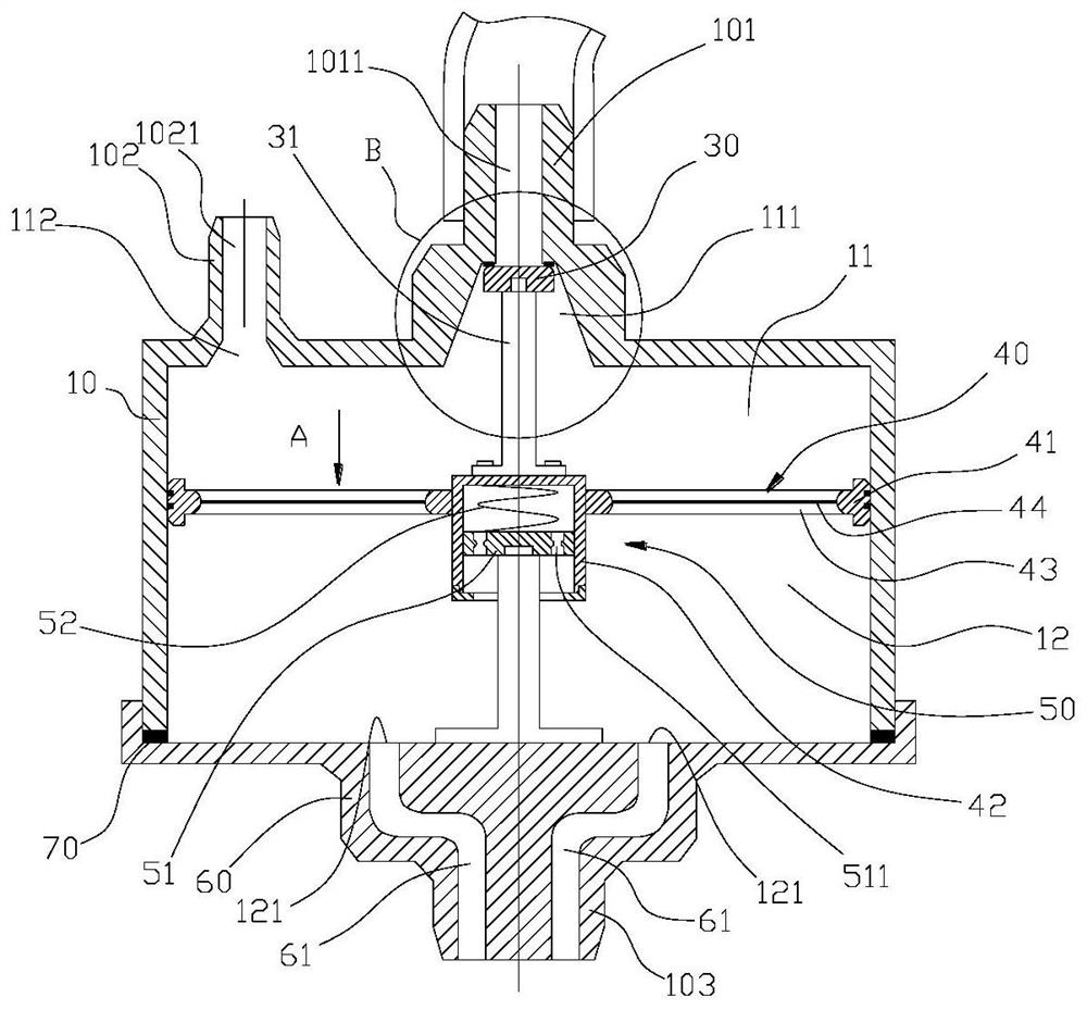
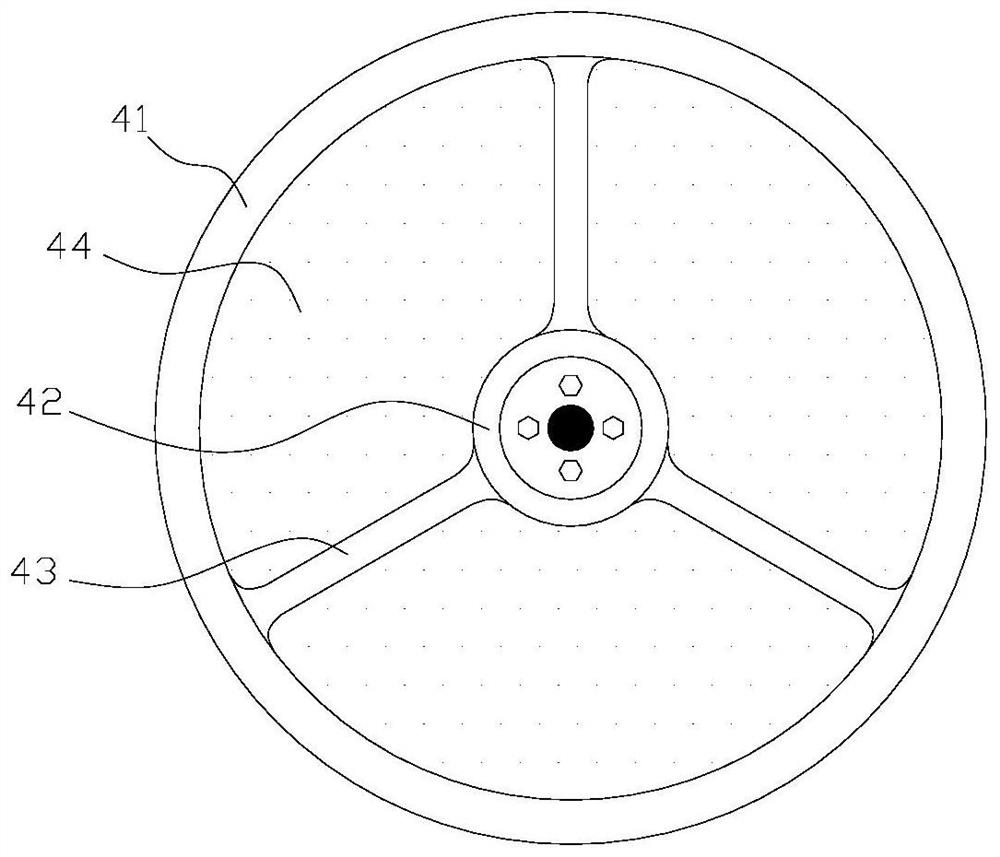
[0071] The embodiment of the present invention discloses an exhaust control mechanism 100, which is used to control the exhaust of the gas in the airbag in the cuff 40 of the blood pressure measurement device. Before introducing the exhaust control mechanism 100 of the present invention, the structure and existing problems of the exhaust valve used to control the exhaust of the airbag in the blood pressure measuring device in the prior art will be introduced.

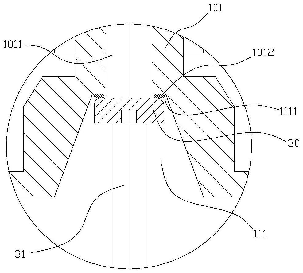
[0072] Such as Figure 16 As shown, the air inlet 702 of the exhaust valve in the prior art is formed at the end of the air intake passage 1011703, the valve core 30701 blocks the air inlet 702 by abutting against the end face 111 of the end, and moves downward To make th...


PUM


Abstract

The invention discloses an exhaust control mechanism and a blood pressure measuring device. The exhaust control mechanism comprises: a first cylinder; a split body, which is arranged in the first cylinder and divides the first cylinder into an upper chamber and an In the lower chamber, the upper end of the first cylinder has a first air inlet and an exhaust port both communicating with the upper chamber, and the lower end of the first cylinder has a second air inlet through which the external pressure gas passes. Enter the lower chamber; the valve core is located above the split body and opposite to the first air inlet, and can move up and down with the split body; wherein: the first air inlet is a counterbore, and the counterbore is along the valve The diameter of the core increases in the downward direction, and the valve core moves upwards in the counterbore to block the first air inlet, and moves downward to open the first air inlet. In the present invention, the first air intake hole is set in the shape of a counterbore, thereby reducing the amount of change of the valve core movement to the flow cross section, so that the exhaust control mechanism of the present invention can make the airbag more stable and uniform exhaust .

Description

technical field [0001] The invention relates to the technical field of medical instruments, in particular to an exhaust control mechanism and a blood pressure measuring device with the exhaust control mechanism. Background technique [0002] Blood pressure measuring devices (eg, sphygmomanometers) are widely used, and are equipped in hospitals and homes. The use of a blood pressure measuring device to detect blood pressure enables patients to keep abreast of their own blood pressure conditions to guide medication or seek medical treatment. [0003] A blood pressure measuring device in the prior art generally includes a cuff, a booster pump, a controller, a pressure sensor and an exhaust valve. The cuff is used to bind the patient's upper arm, which is equipped with an air bag, the pressurizing pump is connected with the air bag inlet to inflate the air bag, and the exhaust exhaust is connected with the air bag exhaust port to selectively discharge the air bag. Air, the pre...

Claims


Application Information

Patent Timeline
Patent Type & Authority Patents(China)
IPC IPC(8): A61B5/021A61B5/022
CPCA61B5/02141A61B5/022A61B5/02233A61B5/0235
Inventor 吕彩霞刘杨
Owner 吕彩霞
Why Eureka
Try Eureka