A method of designing a lens
A design method and lens technology, applied in optical components, instruments, optics, etc., can solve the problems of difficult imaging of lenses, deformation of abutting lenses, large deformation of plastic lenses, etc., to increase imaging quality, reduce difficult imaging, and reduce deformation effect
- Summary
- Abstract
- Description
- Claims
- Application Information
AI Technical Summary
Problems solved by technology
Method used
Image
Examples
Embodiment 1
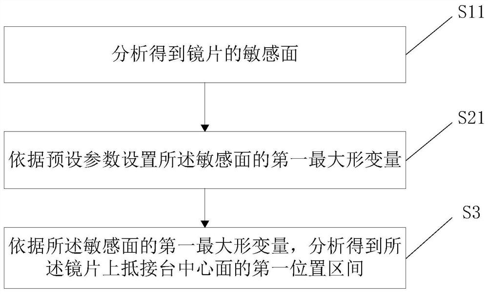
[0094] like figure 1 , Figure 7 and Figure 8 As shown, a method for designing a lens includes the following steps:
[0095] S11, analyze and obtain the sensitive surface of the lens.
[0096] First, calculate the curved surfaces on both sides of the lens, which of the two curved surfaces is more sensitive, and use the more sensitive curved surface as the sensitive surface.
[0097] S21. Set the first maximum deformation amount of the sensitive surface according to preset parameters.
[0098] According to the installation of the first lens L1 to the sixth lens L6 in the lens barrel 1, the focal length, refractive power, image height, aberration and other related parameters of the lens are used as preset parameters to limit the deformation amount of the lens, and then The first maximum deformation amount of the sensitive surface is formed. Therefore, when the deformation amount of the sensitive surface is less than or equal to the first maximum deformation amount, the len...
Embodiment 2
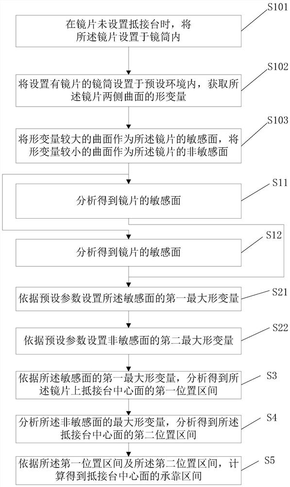
[0103] like figure 1 , figure 2 and Figure 8 As shown, a method for designing a lens includes the following steps:
[0104] S101 , when the lens is not provided with an abutment platform, set the lens in the lens barrel 1 .
[0105] In the current state, the lens is directly arranged in the lens barrel 1, and the lens will deform after abnormal temperature.
[0106] S102. Set the lens barrel 1 provided with the lens in a preset environment, and obtain the deformation amount of the curved surfaces on both sides of the lens.
[0107] The preset environment can be changed according to the user's settings. Specifically, the preset environment mainly refers to different temperature environments. After a period of time, the lens can be deformed, and the user can measure the deformation amount on both sides of the lens.
[0108] S103. Use the curved surface with a larger deformation amount as the sensitive surface of the lens, and use the curved surface with a smaller deformat...
Embodiment 3
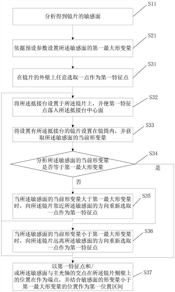
[0120] like image 3 , Figure 7 and Figure 8 As shown, a method for designing a lens includes the following steps:
[0121] S11, analyze and obtain the sensitive surface of the lens.
[0122] S21. Set the first maximum deformation amount of the sensitive surface according to preset parameters.
[0123] S31, arbitrarily select a point on the outer wall of the lens as the first feature point.
[0124] S32, disposing the abutting table on the lens, and making the first feature point fall into the center plane of the abutting table;
[0125] S33. Set the lens provided with the abutting table in the lens barrel 1, and acquire the current deformation amount of the sensitive surface.
[0126] After the abutment table is set on the first feature point, the abutment table is located at one end close to the sensitive surface, and in the current state, the lens is set in the lens barrel 1 again, and the current deformation of the sensitive surface is obtained. The deformation amo...
PUM
 Abstract
Description
Claims
Application Information
 - R&D
- Intellectual Property
- Life Sciences
- Materials
- Tech Scout
- Unparalleled Data Quality
- Higher Quality Content
- 60% Fewer Hallucinations
Browse by: Latest US Patents, China's latest patents, Technical Efficacy Thesaurus, Application Domain, Technology Topic, Popular Technical Reports.
© 2025 PatSnap. All rights reserved.Legal|Privacy policy|Modern Slavery Act Transparency Statement|Sitemap|About US| Contact US: help@patsnap.com


