Municipal road sludge removing device

A technology for cleaning equipment and roads, which is applied to road surface cleaning, cleaning methods, earth movers/excavators, etc., and can solve problems such as time-consuming, labor-intensive, and unclean cleaning

Active Publication Date: 2018-08-10
倡创(上海)咨询管理事务所
View PDF6 Cites 5 Cited by
  • Summary
  • Abstract
  • Description
  • Claims
  • Application Information

AI Technical Summary

Problems solved by technology

[0004] In order to overcome the disadvantage that the existing cleaning methods are manually using tools to clean the silt on the road surface, manual cleaning is not only time-consuming and laborious, but also not clean. The technical problem to be solved by the present invention is to provide a time-saving and labor-saving , Municipal road sludge cleaning equipment with fast cleaning speed

Method used


Image

  • Municipal road sludge removing device
  • Municipal road sludge removing device
  • Municipal road sludge removing device

Examples


Embodiment 1

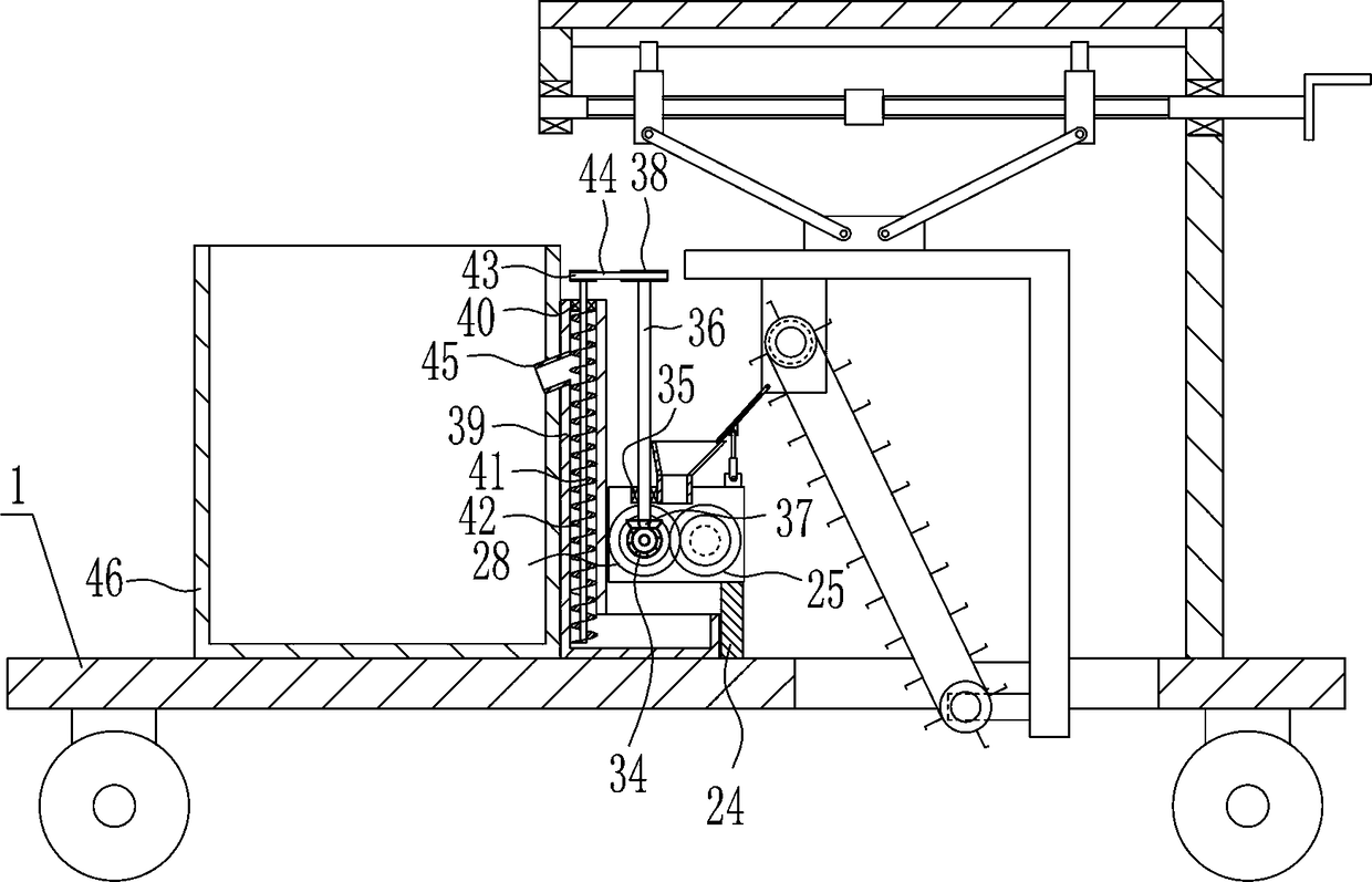
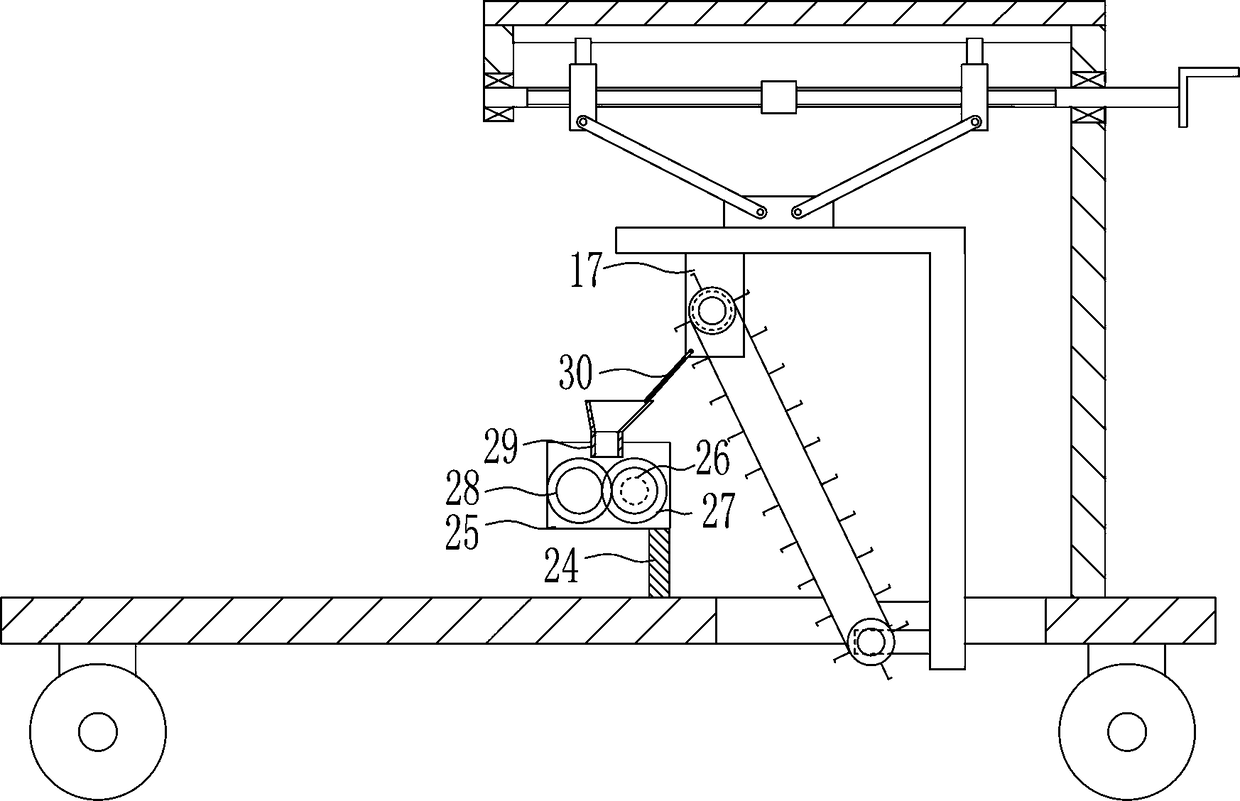
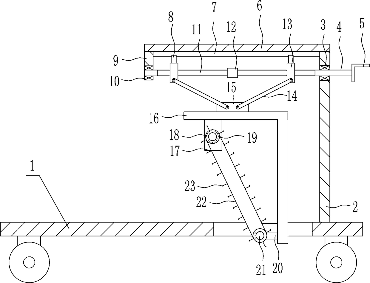
[0026] A municipal road sludge cleaning equipment, such as Figure 1-5 Shown, include vehicle frame 1, first support 2, first bearing 3, right screw rod 4, handle 5, second support 6, slide rail 7, slide block 8, the 3rd support 9, second bearing 10, Left screw 11, coupling 12, nut 13, connecting rod 14, first fixed block 15, support plate 16, first fixed plate 17, first motor 18, first conveyor pulley 19, pole 20, second conveyor belt Wheel 21, transmission belt 22 and transmission frame 23 have a through hole in the right part of the vehicle frame 1, a first support 2 is fixedly connected to the upper right side of the vehicle frame 1, and a first bearing is embedded in the top of the first support 2. 3. The right screw rod 4 is connected to the first bearing 3 with interference, the handle 5 is fixedly connected to the right end of the right screw rod 4, the second bracket 6 is fixedly connected to the top of the first bracket 2, and the second bracket 6 The bottom end is ...

Embodiment 2

[0028] A municipal road sludge cleaning equipment, such as Figure 1-5 Shown, include vehicle frame 1, first support 2, first bearing 3, right screw rod 4, handle 5, second support 6, slide rail 7, slide block 8, the 3rd support 9, second bearing 10, Left screw 11, coupling 12, nut 13, connecting rod 14, first fixed block 15, support plate 16, first fixed plate 17, first motor 18, first conveyor pulley 19, pole 20, second conveyor belt Wheel 21, transmission belt 22 and transmission frame 23 have a through hole in the right part of the vehicle frame 1, a first support 2 is fixedly connected to the upper right side of the vehicle frame 1, and a first bearing is embedded in the top of the first support 2. 3. The right screw rod 4 is connected to the first bearing 3 with interference, the handle 5 is fixedly connected to the right end of the right screw rod 4, the second bracket 6 is fixedly connected to the top of the first bracket 2, and the second bracket 6 The bottom end is ...

Embodiment 3

[0031] A municipal road sludge cleaning equipment, such as Figure 1-5 Shown, include vehicle frame 1, first support 2, first bearing 3, right screw rod 4, handle 5, second support 6, slide rail 7, slide block 8, the 3rd support 9, second bearing 10, Left screw 11, coupling 12, nut 13, connecting rod 14, first fixed block 15, support plate 16, first fixed plate 17, first motor 18, first conveyor pulley 19, pole 20, second conveyor belt Wheel 21, transmission belt 22 and transmission frame 23 have a through hole in the right part of the vehicle frame 1, a first support 2 is fixedly connected to the upper right side of the vehicle frame 1, and a first bearing is embedded in the top of the first support 2. 3. The right screw rod 4 is connected to the first bearing 3 with interference, the handle 5 is fixedly connected to the right end of the right screw rod 4, the second bracket 6 is fixedly connected to the top of the first bracket 2, and the second bracket 6 The bottom end is ...


PUM


Abstract

The invention relates to a removing device, in particular to a municipal road sludge removing device and aims at achieving the technical purposes that the provided municipal road sludge removing device saves time and labor and is high in removing speed. In order to achieve the above technical purposes, the municipal road sludge removing device is provided and comprises a vehicle frame, a first support, a first bearing, a right screw, a crank, a second support, a sliding rail, sliding blocks, a third support, a second bearing, a left screw, a coupler and the like. A through hole is formed in the right portion of the vehicle frame, the first support is fixedly connected to the right side above the vehicle frame, the first bearing is embedded in the upper portion of the first support, the right screw is connected to the inside of the first bearing in an interference fit mode, and the crank is fixedly connected to the right end of the right screw. By the adoption of the municipal road sludge removing device, the function that sludge is removed is achieved, and not only the function that the sludge is quickly removed is achieved, but also the function that the sludge is collected and loaded is achieved.

Description

technical field [0001] The invention relates to a cleaning device, in particular to a municipal road sludge cleaning device. Background technique [0002] After the heavy rain, there will be a lot of mud washed on the road with the rain, forming a thick silt, so it is necessary to clean up the silt. If it is not cleaned up, traffic accidents will easily occur and the road will be paralyzed. The existing cleaning methods are Manually use tools to clean up the silt on the road surface. Manual cleaning is not only time-consuming and laborious, but also difficult to clean. Therefore, there is an urgent need for a municipal road silt cleaning equipment that saves time and effort and has a fast cleaning speed. Contents of the invention [0003] (1) Technical problems to be solved [0004] In order to overcome the disadvantage that the existing cleaning methods are manually using tools to clean the silt on the road surface, manual cleaning is not only time-consuming and laboriou...

Claims


Application Information

Patent Timeline
Patent Type & Authority Applications(China)
IPC IPC(8): E01H1/04E02F3/08E02F3/12E02F5/30
Inventor 魏亦南
Owner 倡创(上海)咨询管理事务所
Why Eureka
Try Eureka