Intelligent distribution box for electrical equipment

A technology for electrical equipment and distribution boxes, applied in electrical components, circuit devices, climate sustainability, etc., can solve problems such as the inability to support dynamic adjustment of electricity load, and achieve convenient access to backup power and ensure electricity safety. Effect

Pending Publication Date: 2018-08-10
逯帅
View PDF6 Cites 7 Cited by
  • Summary
  • Abstract
  • Description
  • Claims
  • Application Information

AI Technical Summary

Problems solved by technology

[0008] The purpose of the present invention is to provide an intelligent distribution box for electrical equipment to solve the problem that the existing distribution box cannot support the dynamic adjustment of electric load

Method used


Image

  • Intelligent distribution box for electrical equipment
  • Intelligent distribution box for electrical equipment

Examples


Embodiment 1

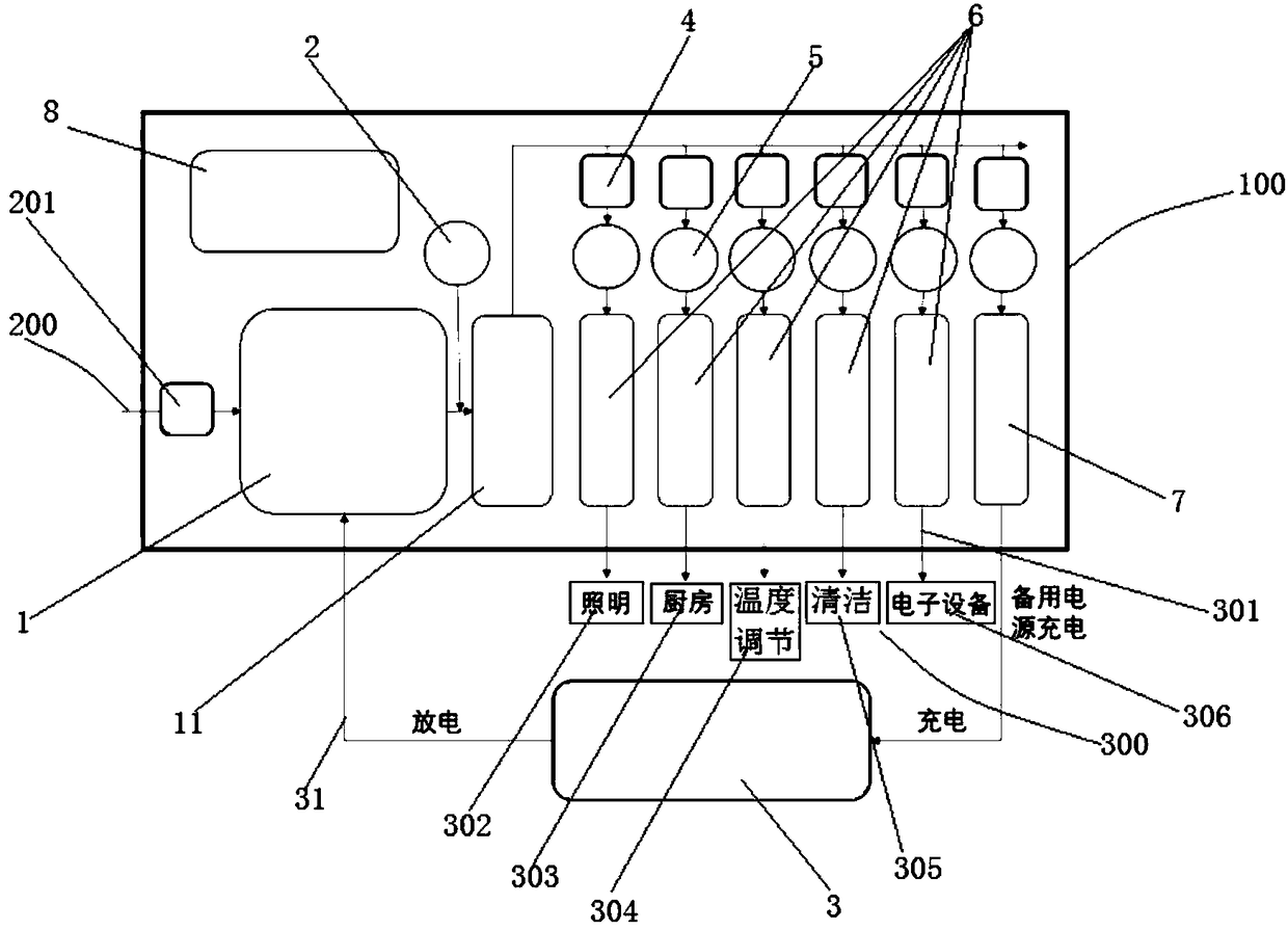
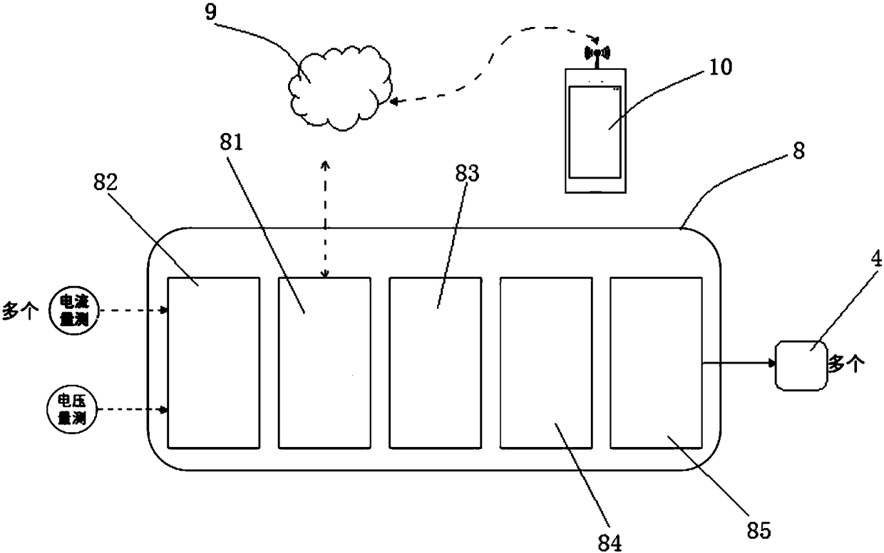
[0032] see Figure 1 ~ Figure 2, an intelligent distribution box for electrical equipment provided by the present invention, the distribution box includes: a box body 100; A voltage measurement module 2, connected to the output end of the power switch 1; a backup power supply 3, arranged outside the box 100, whose output end is electrically connected to the other input end of the power switch 1; several current measurement modules 5. The input terminals are respectively connected in series with the output terminals of a load control relay 4; several load circuit breakers 6, each group including at least one circuit breaker, the input terminals are respectively connected in series with the output terminals of a current measurement module 5, and the output terminals are respectively connected with a class of The electrical equipment 300 is electrically connected to form several groups of electrical load circuits 301; a backup power circuit breaker 7, the input end of which is co...

Embodiment 2

[0042] An incoming line control relay 201 is arranged between the power conversion switch 1 and the incoming line 200 , and the incoming line control relay 201 is communicatively connected with the intelligent controller 8 . All the other are with embodiment 1.

Embodiment 3

[0044] The output end of the power transfer switch 1 is also connected in series with a main circuit breaker 11, the voltage measurement module 2 is connected in series with the output end of the power transfer switch 1 and then connected in parallel with the main circuit breaker 11, the backup power circuit breaker 7 and Several load circuit breakers 6 are respectively connected in series with the output end of the main circuit breaker 11 . All the other are with embodiment 1.


PUM


Abstract

The invention relates to an intelligent distribution box for electrical equipment, and the distribution box comprises a box body; a power change-over switch which is disposed in the box body, whereinone input end is electrically connected with a service entrance conductor; a voltage measurement module which is connected to the output end of the power change-over switch in a parallel manner; a standby power supply, wherein the output end of the standby power supply is electrically connected with the power change-over switch; a plurality of load control relays, wherein the input ends of the load control relays are in series connection with the power change-over switch; a plurality of current measurement modules, wherein the input ends of the current measurement modules are in series connection with the load control relays; a standby power circuit breaker, wherein the input end of the standby power circuit breaker is in series connection with one current measurement module, and the output end of the standby power circuit breaker is electrically connected with the standby power supply; a plurality of load circuit breakers; an intelligent controller; a cloud server which is in communication connection with the intelligent controller; and a mobile terminal APP which is in communication connection with the cloud server. Compared with a conventional common distribution box, the distribution box has the additional functions of load classification, intelligent dynamic load control, standby power access and conversion and remote communication and control.

Description

technical field [0001] The invention belongs to the technical field of distribution boxes, and in particular relates to an intelligent distribution box for electrical equipment. Background technique [0002] The distribution boxes in existing residential, commercial or office places only have basic functions such as connecting the incoming line and electrical equipment, as well as overload and leakage protection; a few manufacturers have begun to provide intelligent distribution boxes with remote control switch opening and closing functions. [0003] Problems and disadvantages of prior art: [0004] 1) The existing intelligent distribution box has no load classification function, and the load type of each line needs to be manually set during remote control, which is arbitrary; [0005] 2) The existing power distribution box does not have a circuit specially designed for connecting the backup power supply, so it cannot be connected to and use the backup power supply; [000...

Claims


Application Information

Patent Timeline
Patent Type & Authority Applications(China)
IPC IPC(8): H02B1/46H02J9/06H02J13/00
CPCH02J13/0013H02B1/46H02J9/06Y04S20/12Y04S20/242Y04S20/248Y02B70/30Y02B90/20Y04S20/20
Inventor 逯帅
Owner 逯帅
Why Eureka
Try Eureka