
Paint stirring device for petroleum pipeline production processing paint spraying

A stirring device and oil pipeline technology, applied to mixers with rotating stirring devices, mixer accessories, transportation and packaging, etc., can solve problems such as the burden of carrying sprayers, paint quality problems, and the inability to effectively handle paint debris and dross

Inactive Publication Date: 2018-08-14
ANHUI UNIVERSITY OF TECHNOLOGY AND SCIENCE
View PDF6 Cites 2 Cited by
  • Summary
  • Abstract
  • Description
  • Claims
  • Application Information

AI Technical Summary

Problems solved by technology

[0004] Aiming at the deficiencies in the prior art, the purpose of the present invention is to provide a paint stirring device for oil pipeline production and processing to spray paint, so as to solve the problem that the existing paint stirring device is relatively easy to use, cannot effectively handle the debris inside the paint, and is easy to make the paint There are quality problems, and it is easy to cause a burden on the carrying sprayer and reduce the service life when it is used later

Method used


Image

  • Paint stirring device for petroleum pipeline production processing paint spraying
  • Paint stirring device for petroleum pipeline production processing paint spraying
  • Paint stirring device for petroleum pipeline production processing paint spraying

Examples


Embodiment Construction

[0023] In order to make the technical means, creative features, goals and effects achieved by the present invention easy to understand, the present invention will be further described below in conjunction with specific embodiments.

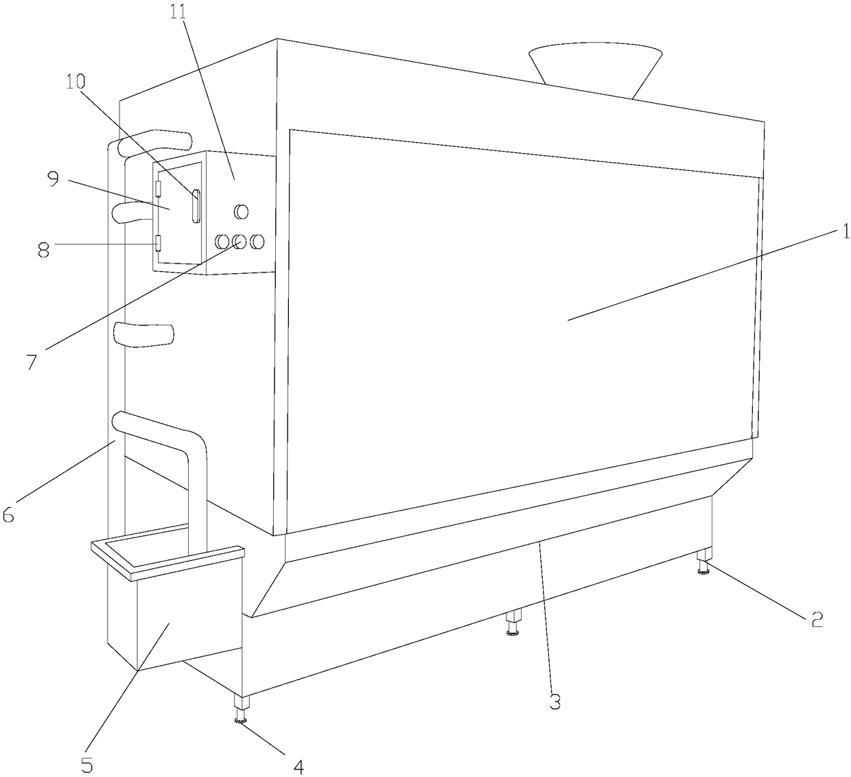
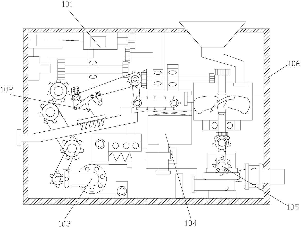
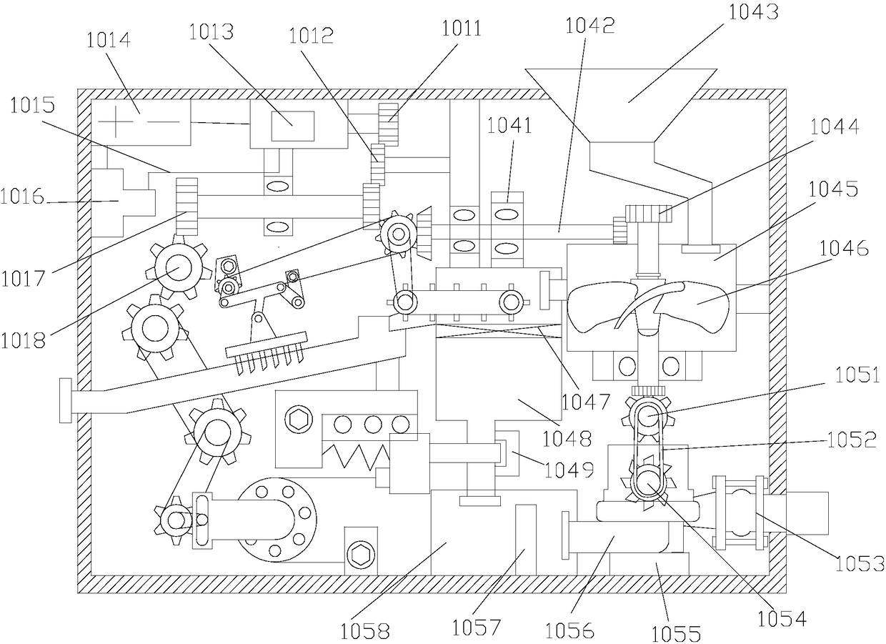
[0024] see Figure 1-Figure 4, the present invention provides a technical scheme of a paint stirring device for oil pipeline production and processing painting: its structure includes a paint stirring device 1, a load-bearing rod 2, a base 3, a non-slip mat 4, a sewage collection box 5, a sewage collection pipe 6, and an operation button 7 , hinge 8, box door 9, lockset 10, operation box 11, the top of the load-bearing bar 2 is welded to the bottom of the base 3, the top of the load-bearing bar 2 is vertically connected to the bottom of the base 3, and the inside of the anti-skid pad 4 is connected to the load-bearing The bottom of the rod 2 is embedded connection, the right end of the sewage collection box 5 is welded to the left end of the base ...


PUM


Abstract

The invention discloses a paint stirring device for petroleum pipeline production processing paint spraying. The paint stirring device structurally comprises a paint stirring device body, a bearing bar, a base, an antiskid pad, a sewage collecting tank, a sewage collecting pipe, an operation key, a hinge, a box door, a lock and an operating box, wherein the top of the bearing bar is in welded connection with the bottom of the base, the top of the bearing bar and the bottom of the base are perpendicularly connected, the inside of the antiskid pad and the bottom of the bearing bar are in embedded type connection, the right end of the sewage collecting tank is in welded connection with the left end of the base, the bottom of the sewage collecting pipe and the inside of the sewage collecting tank are in attachment, and the top of the base and the bottom of the paint stirring device body are fixedly connected through a screw. The paint stirring device for the petroleum pipeline production processing paint spraying disclosed by the invention is structurally provided with the paint stirring device body, the device body can effectively extract residues in a paint material out, and a paintspraying device is prevented from being damaged by the residues; meanwhile, cutoff type feeding can prevent internal air pressure from being too high, extrusion to internal parts is reduced, and service life is prolonged.

Description

technical field [0001] The invention relates to a paint stirring device for producing and processing oil pipelines and belongs to the field of paint stirring devices. Background technique [0002] The paint mixer is one of the components of the paint production equipment, that is, the mixing system. The paint mixer crushes, disperses, emulsifies, and mixes the paint. It is a new type of high-efficiency mixing equipment that operates at high speed through the upper and lower teeth of the dispersion plate. It has the functions of shearing, impacting, crushing and dispersing to achieve rapid mixing, dissolving, dispersing and refining. It is an efficient equipment for stirring, dispersing and dissolving solids such as paint. [0003] However, the existing paint mixing device is relatively easy to use, and cannot effectively deal with debris and dross inside the paint, which is likely to cause quality problems in the paint, and it is easy to cause a burden on the load-bearing sp...

Claims


Application Information

Patent Timeline
IPC IPC(8): B01F7/18B01F15/00B01F15/02B01D36/04
CPCB01D36/04B01F27/1125B01F27/213B01F27/90B01F35/323B01F35/3204B01F35/71731B01F2101/30
Inventor 王军倪维维
Owner ANHUI UNIVERSITY OF TECHNOLOGY AND SCIENCE
Learn More