Micro-fluidic chip capable of realizing flow rate relying avoidance of liquid drip dimension

A technology of microfluidic chip and droplet size, which is applied in the direction of laboratory containers, laboratory utensils, chemical instruments and methods, etc., and can solve the problems of limited detection and reaction applications, unstable microfluidic chip performance, microfluidic Control technology is difficult to apply and other issues

Inactive Publication Date: 2018-08-14
BEIJING UNIV OF TECH
View PDF4 Cites 17 Cited by
  • Summary
  • Abstract
  • Description
  • Claims
  • Application Information

AI Technical Summary

Problems solved by technology

This not only makes it difficult for microfluidic technology to be suitable for quick and easy manual operation, and limits its application in detection and reaction, but also, the flow velocity provided by commonly used driving devices is fluctuating, which easily leads to poor performance of microfluidic chips. Stablize

Method used


Image

  • Micro-fluidic chip capable of realizing flow rate relying avoidance of liquid drip dimension
  • Micro-fluidic chip capable of realizing flow rate relying avoidance of liquid drip dimension
  • Micro-fluidic chip capable of realizing flow rate relying avoidance of liquid drip dimension

Examples


Embodiment Construction

[0024] The working process and effect of inventing a microfluidic chip capable of realizing droplet size independent of flow will be described in detail below in conjunction with the structural drawings.

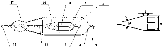
[0025] The specific working process of this chip is as follows: the discrete phase liquid flows in from the discrete phase inlet 5, the continuous phase liquid flows in from the continuous phase inlet 7, and the two meet in the droplet generation chamber 10, and the discrete phase liquid breaks to generate droplets and together with the continuous phase It flows downstream, enters the droplet observation cavity 12 through the main channel, and finally flows out of the chip through the outlet 13 .

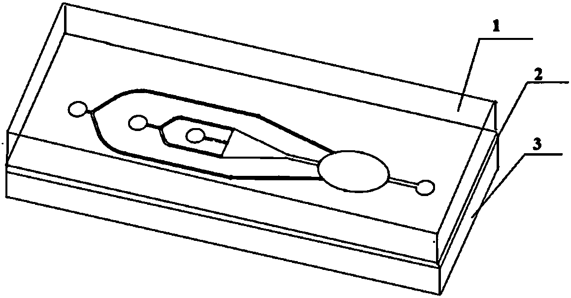
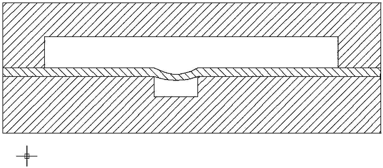
[0026] figure 1 It is a three-dimensional general outline schematic diagram of a microfluidic chip capable of realizing droplet size independent of flow rate in the present invention. figure 2 , image 3 It is a schematic diagram of the working process. There are nine microchan...


PUM


Abstract

The invention discloses a micro-fluidic chip capable of realizing flow rate relying avoidance of liquid drip dimension, and belongs to the technical field of a micro-fluidic chip. The micro-fluidic chip emphasizes the influence of the interface tension and the geometric configuration on the liquid drip generation; the relying of the liquid drip dimension on the speed can be reduced. The micro-fluidic chip comprises an upper layer passage structure, a middle layer and a lower layer passage structure, wherein the upper layer passage is formed by connecting a dispersed phase passage, a continuousphase passage, a liquid drip generating cavity and a liquid drip observation cavity; meanwhile, a Taguchi method is used for reducing the test times; the optimum geometric parameter structure of theliquid drip generation capability is determined. By using the chip, the liquid drip can be uniformly and stably generated without relying on the two-phase flow rate change; the driving limit of the liquid drip generation is facilitated; the chip performance stability maintenance speed range is expanded, so that the micro liquid drip two-phase flow can be applicable to different driving conditions.

Description

technical field [0001] The invention designs a microfluidic chip capable of satisfying that the size of the droplet is not dependent on the flow rate based on the channel structure for generating microdroplets induced by interfacial tension, and belongs to the technical field of microfluidic chips. Background technique [0002] Microfluidic chip refers to the science and technology involved in using micropipes (tens to hundreds of microns in size) to process or manipulate tiny fluid systems. It is a subject involving chemistry, fluid physics, microelectronics, new materials, biology and the emerging interdiscipline of biomedical engineering. Compared with the traditional analysis platform, the micro-droplets prepared by the microfluidic chip can effectively reduce the cost of the experiment. Only a small amount is used in the experiment, which can greatly save the use of expensive biochemical reagents, and has good monodispersity ; Accurate and controllable, uniform size; f...

Claims


Application Information

Patent Timeline
Patent Type & Authority Applications(China)
IPC IPC(8): B01L3/00
CPCB01L3/502784B01L3/502707B01L3/50273
Inventor 刘赵淼赵静逄燕
Owner BEIJING UNIV OF TECH
Why Eureka
Try Eureka