Control method for realizing efficient idle operation in laser pipe cutter

A control method and technology of pipe cutting machine, applied in the direction of digital control, laser welding equipment, electrical program control, etc., can solve the problems of processing efficiency discount, collision, long processing time, etc.

Active Publication Date: 2018-08-14
FOSHAN HONGSHI LASER TECH CO LTD
View PDF4 Cites 12 Cited by
  • Summary
  • Abstract
  • Description
  • Claims
  • Application Information

AI Technical Summary

Problems solved by technology

In such a control cycle, the risk of collision between the cutting head and the pipe can be effectively avoided, but the invalid processing time is long, and the processing efficiency is greatly reduced
[0004] This kind of air movement meth...

Method used


Image

  • Control method for realizing efficient idle operation in laser pipe cutter
  • Control method for realizing efficient idle operation in laser pipe cutter
  • Control method for realizing efficient idle operation in laser pipe cutter

Examples


Embodiment Construction

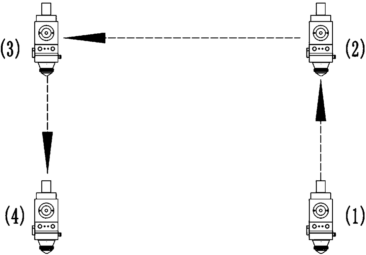
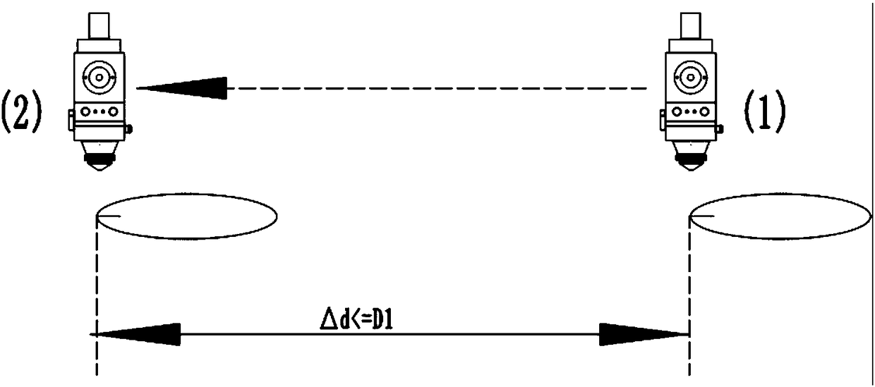
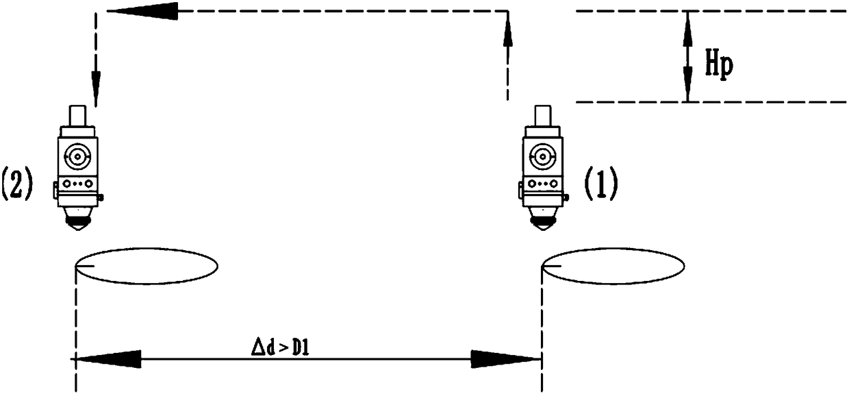
[0035] The flow chart of a control method for realizing high-efficiency dry operation in a laser pipe cutting machine is as follows Figure 7 As shown, the pipe nesting software outputs four different control codes according to the cutting contour, and the CNC system controls the cutting head to perform four different ways of empty movement. Before the air movement starts, the parameters that need to be set include the generalized diameter TD of the pipe, that is, the minimum enclosing circle diameter of the pipe section, the Z-axis air-moving safety offset height Hs, the Z-axis gun safety offset height Ha, and the translation safety offset height Hp, the Z-axis height Ht on the surface of the pipe, the maximum distance of translation D1, the maximum distance of frog jump D2, the direction of pipe rotation is the A direction, where the zero point coordinate of the Z-axis is Z0, that is, the chuck rotation center is the zero point of the Z-axis; including the following step:

...


PUM


Abstract

The invention provides a control method for realizing efficient idle-moving in a laser pipe cutter. The generalized diameter TD of a pipe is involved, namely the minimum encirclement ring diameter ofthe section of the pipe; the Z-axis idle-moving safe offset height Hs, the Z-axis gun-removing safe offset height Ha, the horizontal-moving safe offset height Hp, the pipe surface Z-axis height Ht, the maximum horizontal-moving distance D1 and the maximum leapfrog distance D2 are set, and the pipe rotating direction is the direction A; according to position information between the current contourand the next contour, four different idle-moving codes are output, namely direct horizontal moving, gun-raising horizontal moving, leapfrog idle moving and portal idle moving; and a numerical controlsystem is matched with a height sensing system to control all axes to complete different idle moving processes according to the different idle-moving codes, and on the premise of guaranteeing safety,ineffective machining time is shortened, and the idle-moving efficiency is improved to the maximum.

Description

technical field [0001] The invention relates to the field of laser pipe cutting machines, in particular to a control method for realizing high-efficiency dry running in the laser pipe cutting machine. Background technique [0002] Laser pipe cutting machine is a special equipment for cutting, welding, marking, engraving, surface treatment, fine processing and other processes of pipes by using high-energy laser beams. The laser pipe cutting machining system consists of at least six parts, namely the pipe cutting machine body, chuck, laser, laser cutting head, height tracking system, electrical control system, etc. In the current processing technology, the energy consumption of equipment and the loss of auxiliary materials are relatively large. When this part of loss cannot be reduced, how to control the ratio of the actual effective processing time to the total processing time and reduce the processing time of single parts and the entire pipe, becomes particularly important....

Claims


Application Information

Patent Timeline
IPC IPC(8): B23K26/38G05B19/19B23K101/06
CPCB23K26/38G05B19/19
Inventor 夏宇锐刘洋罗少春常勇
Owner FOSHAN HONGSHI LASER TECH CO LTD
Why Eureka
Try Eureka