
Automated simple mechanical gripper

A mechanical claw and simple technology, applied in the directions of manipulators, chucks, manufacturing tools, etc., can solve the problems of easy impact damage to control elements, insufficient grasping firmness of the mechanical claw, no anti-collision structure, etc. The effect of good grasping firmness and low production cost

Active Publication Date: 2018-08-14
WEIFANG UNIVERSITY
View PDF5 Cites 1 Cited by
  • Summary
  • Abstract
  • Description
  • Claims
  • Application Information

AI Technical Summary

Problems solved by technology

[0003] The purpose of the present invention is to provide an automated simple mechanical claw to solve the problem that the combination of manual and automatic control cannot be performed in the above-mentioned background technology, which makes the use of the mechanical claw relatively inconvenient, and there is no anti-collision structure, so that the mechanical claw is During the control process, the control components are vulnerable to impact damage, and the single claw structure makes the grasping firmness of the mechanical claws insufficient, etc.

Method used


Image

  • Automated simple mechanical gripper
  • Automated simple mechanical gripper
  • Automated simple mechanical gripper

Examples


Embodiment Construction

[0015] The following will clearly and completely describe the technical solutions in the embodiments of the present invention with reference to the accompanying drawings in the embodiments of the present invention. Obviously, the described embodiments are only some, not all, embodiments of the present invention. Based on the embodiments of the present invention, all other embodiments obtained by persons of ordinary skill in the art without making creative efforts belong to the protection scope of the present invention.

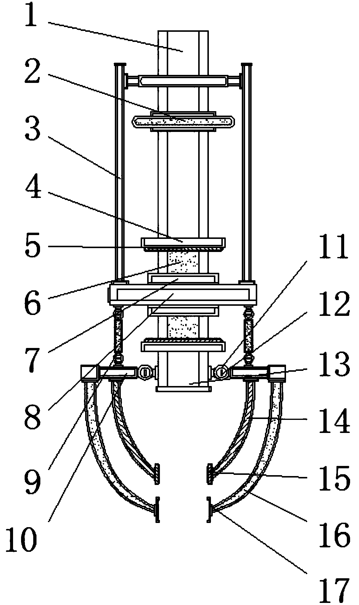
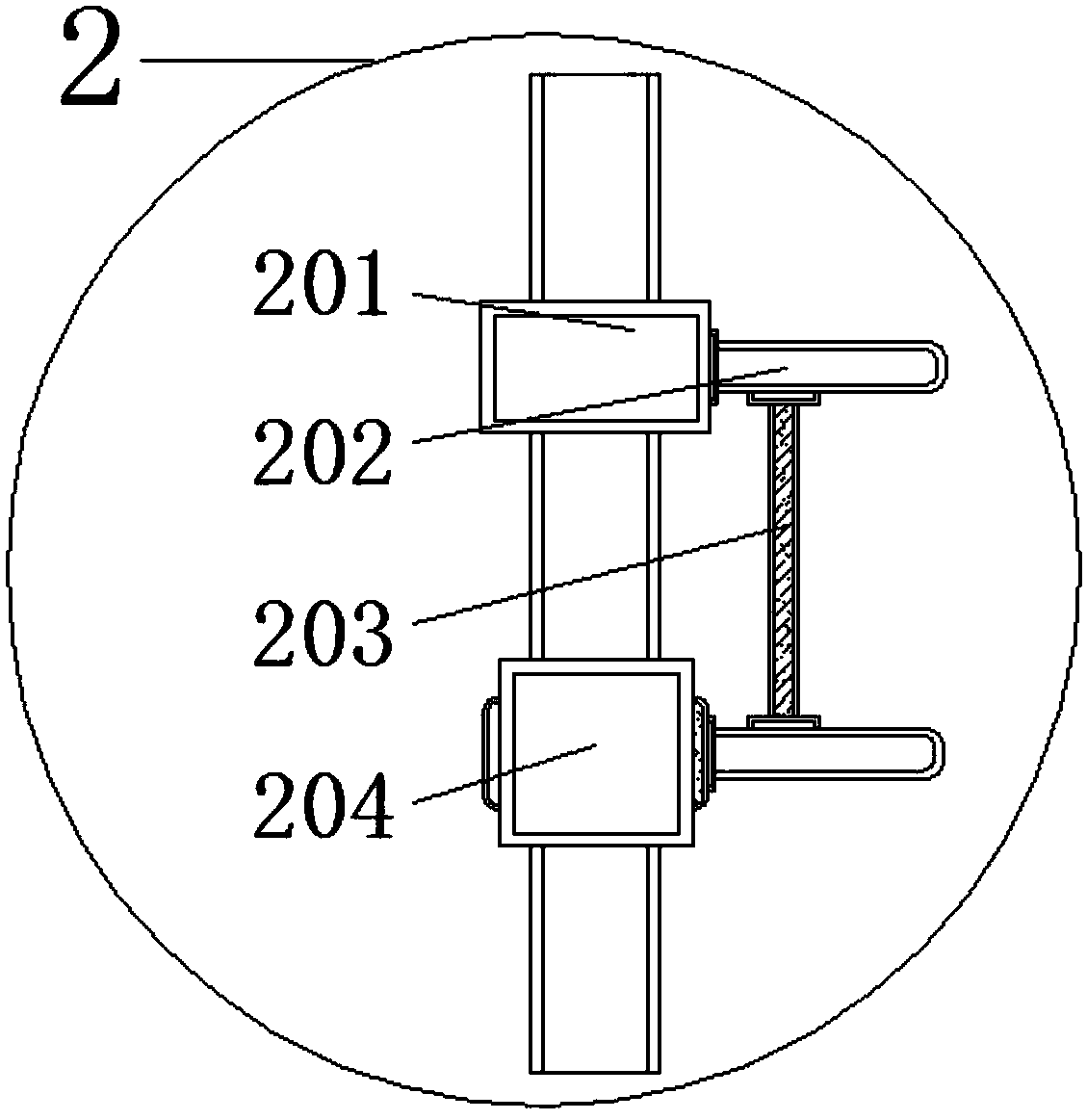
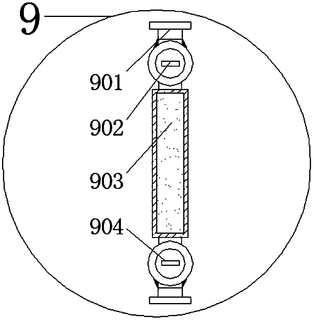
[0016] see Figure 1-3 , an embodiment provided by the present invention: an automated simple mechanical claw, including a main rod body 1, an anti-collision bar 4, a transmission connecting frame 9, a first claw body 14 and a second claw body 16, and the outer side of the main rod body 1 A hand control frame 2 is provided, and control rods 3 are inlaid at the ports on both sides of the hand control frame 2. The hand control frame 2 includes a movable ring 201...


PUM


Abstract

The invention discloses an automated simple mechanical gripper. The automated simple mechanical gripper comprises a main rod body, an anti-collision rod, transmission connecting frames, first gripperbodies and second gripper bodies; a manual control frame is arranged on the outer side of the main rod body, and control rods are inlaid into ports on the two sides of the manual control frame separately; the main rod body is inlaid into the inner side of the anti-collision rod; a moving slide rod is arranged on the inner side of an anti-collision gasket, and the outer side of the moving slide rodis wrapped with a slide sleeve; a central fixing frame and a connecting rod are arranged at ports on the two sides of each transmission connecting frame; a locking rod is inlaid into the inner side of each rotating bearing; and the corresponding connecting rod and a first adsorption end are arranged at ports on the two sides of each first gripper body, and a second adsorption end is inlaid into the bottom end of each second gripper body. According to the automated simple mechanical gripper, the detachable manual control frame is arranged, therefore, the mechanical gripper can be manually controlled to conduct gripping work through the manual control frame, use is relatively convenient, the structure is relatively simple, the manufacture cost is low, and the automated simple mechanical gripper is suitable for large-scale production and use.

Description

technical field [0001] The invention relates to the technical field of mechanical claw equipment, in particular to an automated simple mechanical claw. Background technique [0002] Machinery refers to the general term of machines and mechanisms. Machinery is a tool device that can help people reduce the difficulty of work or save labor. Items such as chopsticks, brooms, and tweezers can be called machinery. They are simple machines, and complex machines are made of Two or more simple machines are usually called machines. From the point of view of structure and movement, there is no difference between a mechanism and a machine. It is generally called a machine. With the development of science and technology, a large number of In the production and life of people with continuous application of mechanized equipment, mechanical claws are commonly used as a kind of mechanical equipment. The traditional mechanical claws are used in a single way and cannot be combined with manual ...

Claims


Application Information

Patent Timeline
Patent Type & Authority Applications(China)
IPC IPC(8): B25J15/00B25J15/02B25J1/06
CPCB25J1/06B25J15/0052B25J15/0206
Inventor 宋健解福祥孙学岩
Owner WEIFANG UNIVERSITY
Learn More