Ceiling fan lamp

A ceiling fan lamp and fan technology, applied in the field of ceiling fan lamps, can solve the problems of insufficient smoothness of blade deployment and storage, large tooth resistance, and cumbersome installation, so as to achieve smooth blade deployment and storage, large tooth resistance, and connection and installation. solid effect

Active Publication Date: 2018-08-14
ZHONGSHAN BAOSHAN ELECTRICAL APPLIANCE CO LTD
View PDF8 Cites 4 Cited by
  • Summary
  • Abstract
  • Description
  • Claims
  • Application Information

AI Technical Summary

Problems solved by technology

However, the ceiling fan lamp with the above-mentioned structure has the following disadvantages: (1) the blades are installed on the blade support through the pivot shaft, the planetary gear and the sun gear, the structure is complex and the installation is cumbersome; The planetary gear and the sun gear are meshed and rotated to drive, which will generate a lot of noise during operation, and the resistance of the teeth is large, the smoothness of blade deployment and storage is not enough, and it is easy to wear and has a short life

Method used


Image

  • Ceiling fan lamp
  • Ceiling fan lamp
  • Ceiling fan lamp

Examples


Embodiment Construction

[0033] The present invention will be further described below in conjunction with the accompanying drawings and embodiments.

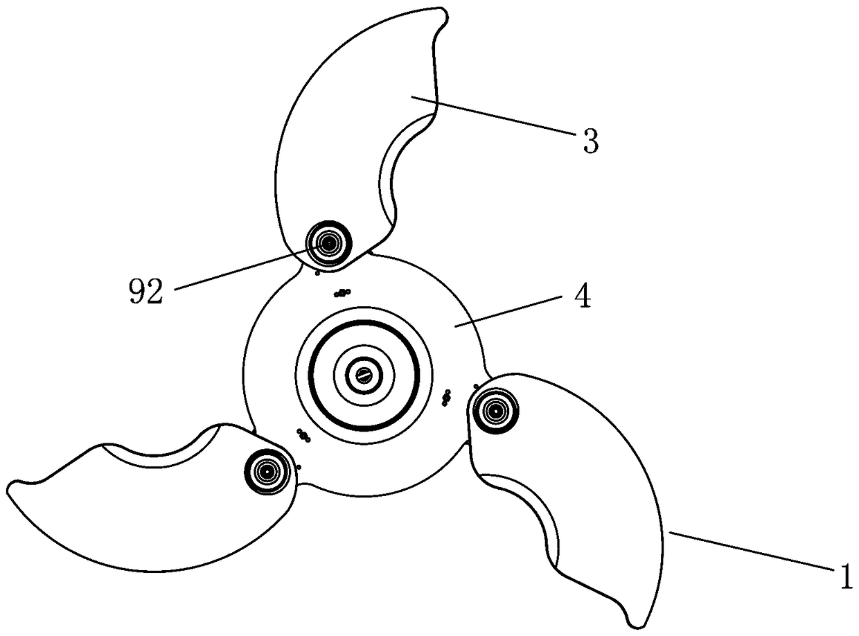
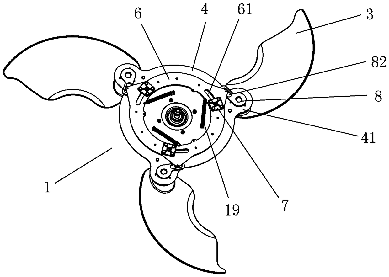
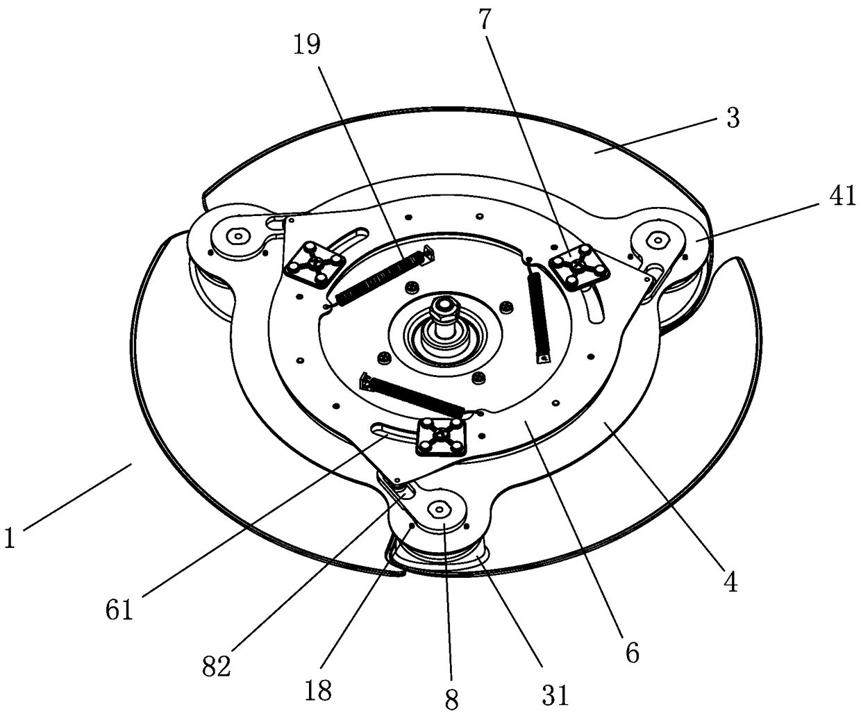
[0034] Such as Figure 1 to Figure 8 As shown, a ceiling fan lamp includes a fan part 1 and a lamp part 2. The fan part 1 includes a fan blade 3, a storage tray 4 and a motor 5. The motor 5 drives the storage tray 4 to rotate, and the fan blade 3 is movably installed on the upper part of the storage tray 4, and is characterized in that it also includes a rotating base 6, a limit slider 7, a push arm 8, a connecting assembly 9 and a sliding block 10, and the rotating base 6 and the sliding block 10 are respectively arranged on the lower part of the storage tray 4, the limit slide 61 is opened on the said rotating base 6, the limit slide 7 is placed on the limit slide 61, and the limit slide 7 is connected to the Storage tray 4, the push arm 8 is provided with a swing hole 81 and a push groove 82, the connecting assembly 9 is connected to the fan blade 3...


PUM


Abstract

The invention discloses a ceiling fan lamp. The ceiling fan lamp comprises a fan part and a lamp part. The fan part comprises fan blades, a storage disc and a motor. The motor drives the storage discto rotate. The fan blades are movably mounted at the upper part of the storage disc. The ceiling fan lamp is characterized in that the ceiling fan lamp further comprises a rotating seat, a limiting sliding block, a pushing arm, a connecting assembly and a sliding block. The rotating seat and the sliding block are arranged at the lower part of the storage disc. A limiting sliding groove is formed in the rotating seat. The limiting sliding block is arranged on the limiting sliding groove and connected with the storage disc. A swinging hole and a pushing groove are formed in the pushing arm. Theconnecting assembly penetrates through the swinging hole in the pushing arm and is connected with the fan blades. The sliding block is arranged on the pushing groove and connected with the rotating seat. The ceiling fan lamp has the advantages that the structure is simple and reasonable, the resistance is small and noise is low when the blades are unfolded, unfolding and storing are smooth, and the service life is long.

Description

technical field [0001] The invention relates to the technical field of ceiling fan lamps. Background technique [0002] Decorative ceiling fans are commonly known as ceiling fan lamps, which are a combination of lamps and ceiling fans, which not only have the lighting and decoration functions of lamps, but also have the blowing effect of fans. At present, the best-seller on the market is a kind of invisible ceiling fan lamp that can hide the blades. The advantage of this invisible ceiling fan lamp is that when the user does not use the fan function, the blades will be automatically folded and hidden (stored) without affecting the appearance. When the user uses the fan function, the blades rotate with the turntable, and the blades are thrown out under the action of centrifugal force, that is, the blades unfold. [0003] See Chinese Invention Patent No.: 200680032396.1, title: combined light fixture and ceiling fan, the ceiling fan light uses a sun gear mounted to the blade s...

Claims


Application Information

Patent Timeline
Patent Type & Authority Applications(China)
IPC IPC(8): F04D25/08F04D29/32F04D29/34F04D29/66F04D29/056F21V33/00
CPCF04D25/08F04D25/088F04D29/056F04D29/325F04D29/34F04D29/388F04D29/663F04D29/665F04D29/666F21V33/0096
Inventor 高用忠谢刚罗金林
Owner ZHONGSHAN BAOSHAN ELECTRICAL APPLIANCE CO LTD
Why Eureka
Try Eureka