An Image Array Optical Flow Estimation Method for Artificial Compound Eye Camera

A compound eye camera and image array technology, applied in the field of computer vision, can solve the problems of inconsistent optical flow field, lack of supporting information, poor image edge estimation results, etc., and achieve the effect of solving inaccurate image edge optical flow estimation

Inactive Publication Date: 2020-06-02
SOUTHWEST JIAOTONG UNIV
View PDF7 Cites 0 Cited by
  • Summary
  • Abstract
  • Description
  • Claims
  • Application Information

AI Technical Summary

Problems solved by technology

[0003] Although there are a large number of optical flow estimation methods, there are still many problems in the application of artificial compound eye camera images.
Due to the characteristics of multiple low-resolution imaging channels of the artificial compound eye camera, although there is overlap between adjacent sub-eye images, due to the lack of effective support information, the current optimal optical flow estimation method is used to analyze the artificial compound eye. The optical flow estimation of the image still has the problems of poor image edge estimation results and inconsistent optical flow fields in the corresponding regions of adjacent sub-eyes

Method used


Image

  • An Image Array Optical Flow Estimation Method for Artificial Compound Eye Camera
  • An Image Array Optical Flow Estimation Method for Artificial Compound Eye Camera
  • An Image Array Optical Flow Estimation Method for Artificial Compound Eye Camera

Examples


Embodiment Construction

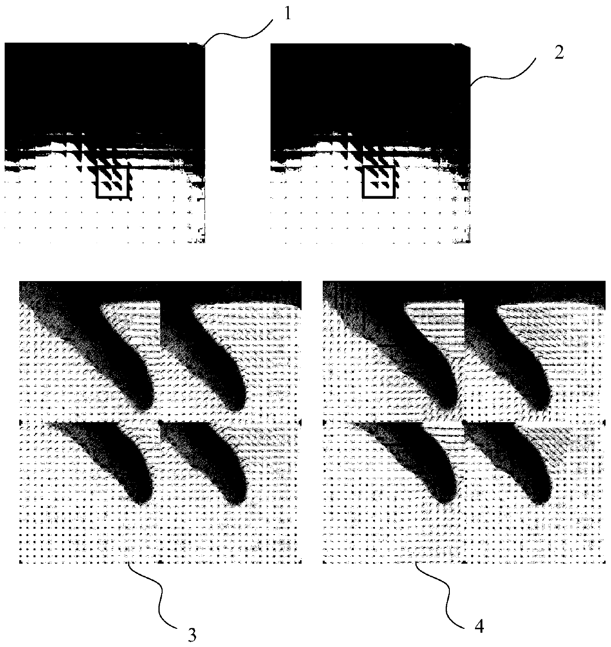
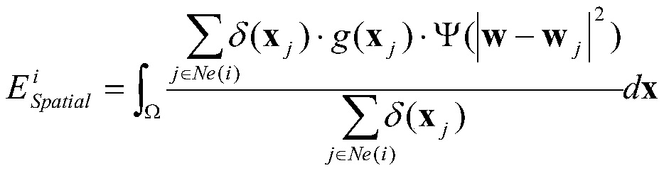
[0052] The present invention will be described in further detail below by way of examples.

[0053] An image array optical flow estimation method for an artificial compound eye camera. According to the structural characteristics of the artificial compound eye, the method constructs an optical flow estimation energy function, effectively constrains the corresponding areas of adjacent sub-eye images, and uses the variational method to estimate the optical flow. Estimate and complete the artificial compound eye image optical flow estimation. In this embodiment, a specific artificial compound eye camera (electronic cluster eye, Electronic cluster eye) is used as an experimental object to estimate the target depth information. The number of electronic cluster eye imaging channels used in the example is 17*13. Due to the influence of distortion, only 13*13 channels of its center are used. The present invention needs to take the following steps:

[0054] S1. Use the electronic cluster...


PUM


Abstract

The invention discloses an image array optical flow estimation method for an artificial compound eye camera. The method comprises the steps of detecting an image comprising a moving target in array images according to structural characteristics of used artificial compound eyes; building an optical flow estimation energy function; and optimizing the energy function by utilizing a variational method, thereby finishing optical flow estimation of artificial compound eye images. Compared with the prior art, the method has the remarkable advantages that an artificial compound eye image sequence canbe effectively subjected to the optical flow estimation, and due to constraint items of spatial correlation among sub-eye images, corresponding regions of adjacent sub-eyes can be constrained to obtain a consistent optical flow estimation result, so that the problem of inaccurate image edge optical flow estimation caused by small view field angle of the sub-eyes in the artificial compound eye camera is solved.

Description

technical field [0001] The invention relates to the technical field of computer vision, in particular to an image array optical flow estimation method of an artificial compound eye camera. Background technique [0002] Vision is an important means for most organisms to understand and perceive the world. As a widespread visual system, insect compound eyes have the characteristics of small size, clear imaging at close range, large field of view, and sensitivity to moving targets. Although traditional monocular cameras have been able to obtain high-definition images, it is difficult to further reduce the size and focal length of monocular cameras. As a new type of camera, the artificial compound eye camera can simulate the imaging principle of insect compound eyes, and can maintain the imaging effect comparable to that of monocular cameras while having a smaller volume. Therefore, the artificial compound eye camera has important research value in moving target estimation and 3...

Claims


Application Information

Patent Timeline
Patent Type & Authority Patents(China)
IPC IPC(8): G06T7/269
CPCG06T7/269
Inventor 张葛祥吴思东荣海娜
Owner SOUTHWEST JIAOTONG UNIV
Why Eureka
Try Eureka