Check patentability & draft patents in minutes with Patsnap Eureka AI!

terminal

A terminal and welding technology, applied in the direction of contact parts, etc., can solve the problems of signal transmission loss of energy, high-frequency signal transmission interference, electromagnetic induction and other problems, to improve the effect of wood piles and reduce electromagnetic induction.

Active Publication Date: 2020-06-05
DEYI PRECISION ELECTRONIC IND CO LTD PANYU
View PDF5 Cites 0 Cited by
  • Summary
  • Abstract
  • Description
  • Claims
  • Application Information

AI Technical Summary

Problems solved by technology

[0002] With the development of electronic technology, the transmission of high-frequency signals is particularly important in the field of electrical connectors. However, there is a common stake effect in terminal design, also called antenna effect. The so-called antenna effect is when the high-frequency signal passes through the electrical connection. When using a device, if the end of the signal terminal is longer, the end of the signal terminal will continue to extend or tilt up after contacting the gold finger on the circuit board. Therefore, the signal will generate electromagnetic induction in the uncontacted part, causing serious signal radiation to the outside world. , signal transmission will lose more energy, which will interfere with the transmission of high-frequency signals. If the end of the signal terminal is short, the end of the signal terminal is not in contact with the end of the gold finger on the circuit board, and the uncontacted part will also generate electromagnetic induction. , so as to interfere with the transmission of high-frequency signals

Method used


Image

  • terminal
  • terminal
  • terminal

Examples


Embodiment Construction

[0028] In order to facilitate a better understanding of the purpose, structure, features, and effects of the present invention, the present invention will now be further described in conjunction with the accompanying drawings and specific embodiments.

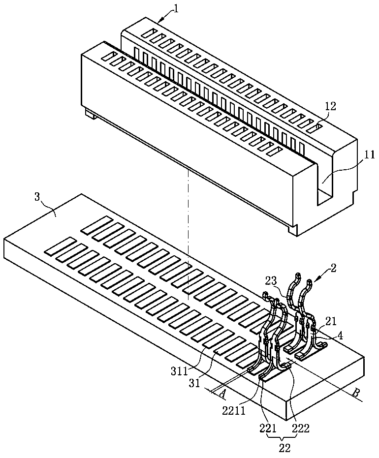
[0029] Such as figure 1 As shown, the terminals of the present invention are mainly used in electrical connectors, such as DDR, PCI or ICSCCKET. It includes an insulating body 1 , at least one terminal 2 , a circuit board 3 , and at least one welding pad 31 , and the terminal 2 is welded on the welding pad 31 .

[0030] Such as Figure 1 to Figure 3 As shown, the insulating body 1 is recessed downward with a slot 11, and a plurality of the terminals 2 are arranged in two rows on opposite sides of the slot 11 for electrically connecting an electronic card (not shown in the figure). ), the insulating body 1 is provided with a plurality of receiving grooves 12 for accommodating each of the terminals 2, the terminal 2 has a base ...


PUM


Abstract

The invention discloses a terminal connected to a circuit board in a conducting manner. At least one welding pad is arranged on the circuit board. The terminal is characterized by comprising: a base part, wherein the base part extends downwards to form a welding part; the welding part comprises a first welding part and a second welding part which are far away from each other; the first welding part and the second welding part are welded with the same welding pad; and the tail end of the first welding part is flush with one end of the welding pad, and the tail end of the second welding part isflush with the other end of the welding pad. According to the terminal disclosed by the invention, the two welding parts are formed by the base part of the terminal, and the two welding parts are respectively flush with the left end and the right end of the same welding pad on the circuit board, thereby reducing electromagnetic induction of the tail end of the terminal or the welding pad of the circuit board and improving a wood pile effect.

Description

technical field [0001] The invention relates to a terminal, in particular to a terminal for transmitting high-frequency signals. Background technique [0002] With the development of electronic technology, the transmission of high-frequency signals is particularly important in the field of electrical connectors. However, there is a common stake effect in terminal design, also called antenna effect. The so-called antenna effect is when the high-frequency signal passes through the electrical connection. When using a device, if the end of the signal terminal is longer, the end of the signal terminal will continue to extend or tilt up after contacting the gold finger on the circuit board. Therefore, the signal will generate electromagnetic induction in the uncontacted part, causing serious signal radiation to the outside world. , signal transmission will lose more energy, which will interfere with the transmission of high-frequency signals. If the end of the signal terminal is s...

Claims


Application Information

Patent Timeline
Patent Type & Authority Patents(China)
IPC IPC(8): H01R13/02
CPCH01R13/02
Inventor 何菲彭治国隆权
Owner DEYI PRECISION ELECTRONIC IND CO LTD PANYU
Features
  • R&D
  • Intellectual Property
  • Life Sciences
  • Materials
  • Tech Scout
  • Unparalleled Data Quality
  • Higher Quality Content
  • 60% Fewer Hallucinations
Learn More