Mechanical clamping jaw

A technology of mechanical gripper and claw head, applied in the field of mechanical gripper, can solve the problems of complex structure of mechanical gripper, inconvenient operation and use, etc., and achieves the effects of convenient operation, convenient production and assembly, and reduced surface damage.

Inactive Publication Date: 2018-08-17
苏州鸣人金属制品有限公司
View PDF0 Cites 0 Cited by
  • Summary
  • Abstract
  • Description
  • Claims
  • Application Information

AI Technical Summary

Problems solved by technology

[0003] The technical problem mainly solved by the present invention is to provide a mechanical gripper, which solves the problems of complex structure and inconvenient operation and use of the mechanical gripper

Method used


Image

  • Mechanical clamping jaw
  • Mechanical clamping jaw

Examples


Embodiment Construction

[0011] The preferred embodiments of the present invention will be described in detail below in conjunction with the accompanying drawings, so that the advantages and features of the present invention can be more easily understood by those skilled in the art, so as to define the protection scope of the present invention more clearly.

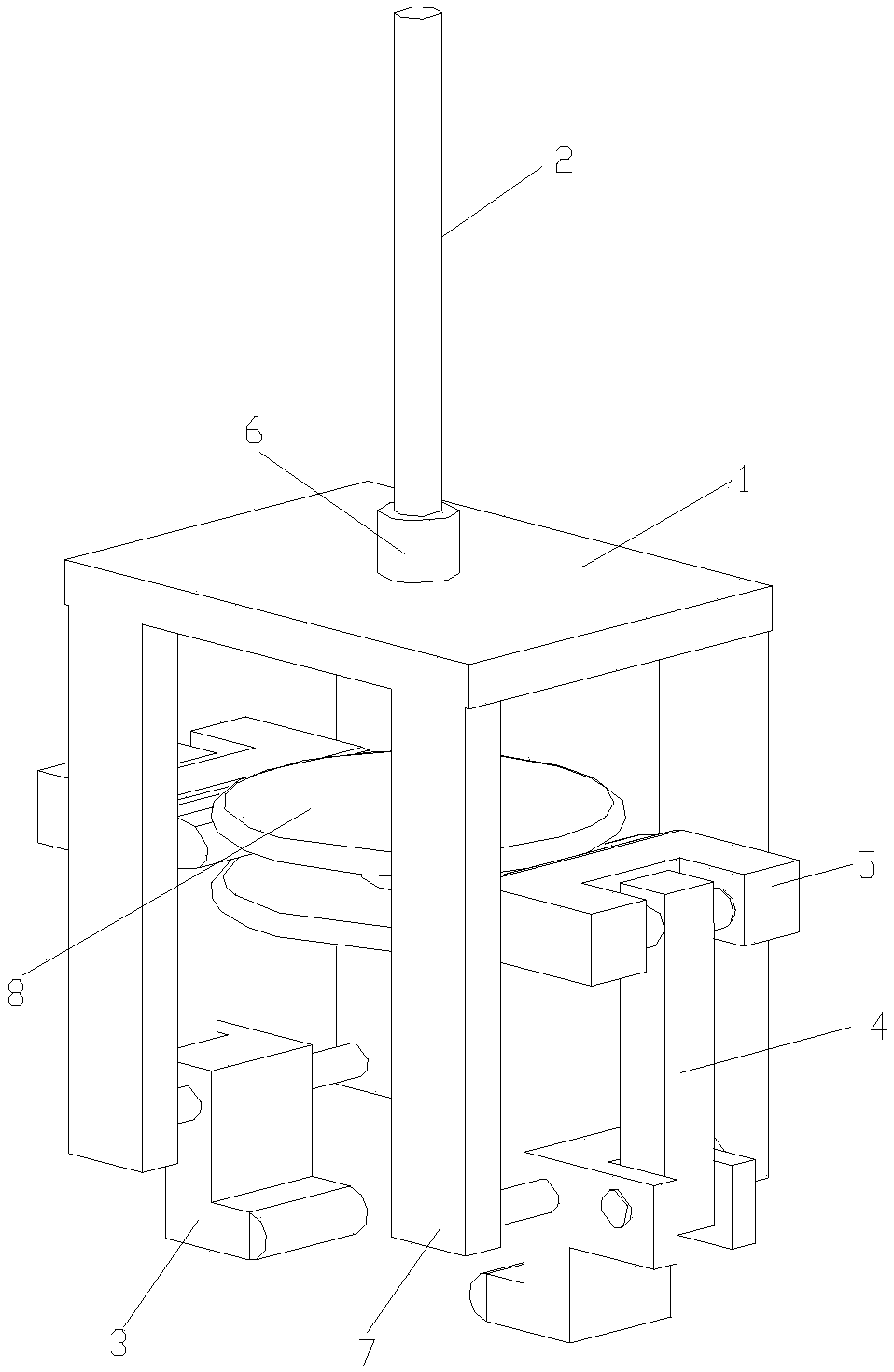
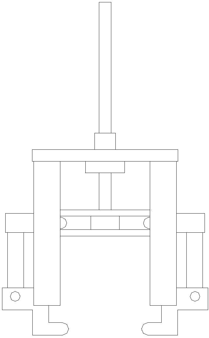
[0012] Please refer to the attached figure 1 and 2 , the embodiment of the present invention includes:

[0013] A mechanical gripper includes a bottom plate 1, a guide rod 2, a claw head 3, a connecting rod 4 and a transmission block 5. The bottom plate 1 is provided with a guide sleeve 6 matching with the guide rod 2, and the guide rod 2 is sleeved in the guide sleeve 6, and the sliding fit can transmit with lower frictional force, reducing energy consumption. On the lower surface of the bottom plate 1, the claw heads 3 are fixed by the support columns 7, and two claw heads 3 are arranged oppositely. The claw head 3 has a Z-shape, and is fixe...


PUM


Abstract

The invention relates to a mechanical clamping jaw. The mechanical clamping jaw comprises a bottom plate, a guide rod, claw heads, connecting rods and a transmission block; a guide sleeve matched withthe guide rod is arranged on the bottom plate, and the guide rod is sleeved with the guide sleeve; the two claw heads are fixed to the lower surface of the bottom plate through supporting columns, arranged oppositely, and each in a Z shape; the break angle positions of the claw heads are fixed to the supporting columns on the two sides of the claw heads through rotating shafts, and the lower endsof the claw heads serve as clamping ends, and the upper ends of the claw heads serve as connecting ends; the two oppositely-arranged claw heads clamp a workpiece through the clamping ends rotating inthe opposite direction, and the connecting ends are hinged to the transmission block through the connecting rods; the transmission block is matched with a transmission head on the guide rod, and thetransmission head is in a disc body shape; the transmission head and the guide rod are coaxially fixed, and a revolving face of the transmission head is provided with a groove matched with the transmission block; and one end of the transmission block is machined into a semi-circular protrusion, the protrusion is inserted into the groove, and the transmission head rotates by taking the protrusion in the groove as the axis.

Description

technical field [0001] The invention relates to the field of mechanical hardware structures, in particular to a mechanical gripper. Background technique [0002] The chuck of the traditional mechanical gripper is rigidly connected with the mechanical arm. During the flow operation, the spatial position of the gripper gripping the part is preset. When two or more parts are stacked in the gripping position of the part, the part will The longitudinal height of the robot arm will be greater than the pre-set pick-up height of the part, and the gripper part of the mechanical gripper will hit the part. Due to the large inertial force during the operation of the robot arm, the part will be damaged, and the gripper will be damaged at the same time. Contents of the invention [0003] The technical problem mainly solved by the present invention is to provide a mechanical gripper, which solves the problems of complicated structure and inconvenient operation and use of the mechanical g...

Claims


Application Information

Patent Timeline
Patent Type & Authority Applications(China)
IPC IPC(8): B25J15/02
CPCB25J15/0206
Inventor 陈桂琴
Owner 苏州鸣人金属制品有限公司
Why Eureka
Try Eureka