A drive mechanism for a reciprocating compressor

A driving mechanism and compressor technology, which is applied to machines/engines, engine components, liquid variable capacity machinery, etc. Reduction in the number of parts and assembly space, which is conducive to small and lightweight effects

Active Publication Date: 2019-04-12
HUAZHONG UNIV OF SCI & TECH
View PDF7 Cites 0 Cited by
  • Summary
  • Abstract
  • Description
  • Claims
  • Application Information

AI Technical Summary

Problems solved by technology

[0004] Aiming at the above defects or improvement needs of the prior art, the present invention provides a driving mechanism for a reciprocating compressor, which, through the research and design of key components such as the specific structure of the swash plate assembly and the specific assembly method of the main shaft assembly, It can effectively solve the problems of high friction coefficient, large amount of wear and difficult material selection of sliding friction pairs under poor lubrication or no lubrication conditions, and meet the requirements of small and lightweight compressors, high speed and high pressure, and no oil lubrication. Small coefficient, good self-lubrication, low heat production, slow temperature rise, etc.

Method used


Image

  • A drive mechanism for a reciprocating compressor
  • A drive mechanism for a reciprocating compressor
  • A drive mechanism for a reciprocating compressor

Examples


Embodiment Construction

[0026] In order to make the objectives, technical solutions, and advantages of the present invention clearer, the following further describes the present invention in detail with reference to the accompanying drawings and embodiments. It should be understood that the specific embodiments described herein are only used to explain the present invention, but not to limit the present invention. In addition, the technical features involved in the various embodiments of the present invention described below can be combined with each other as long as they do not conflict with each other.

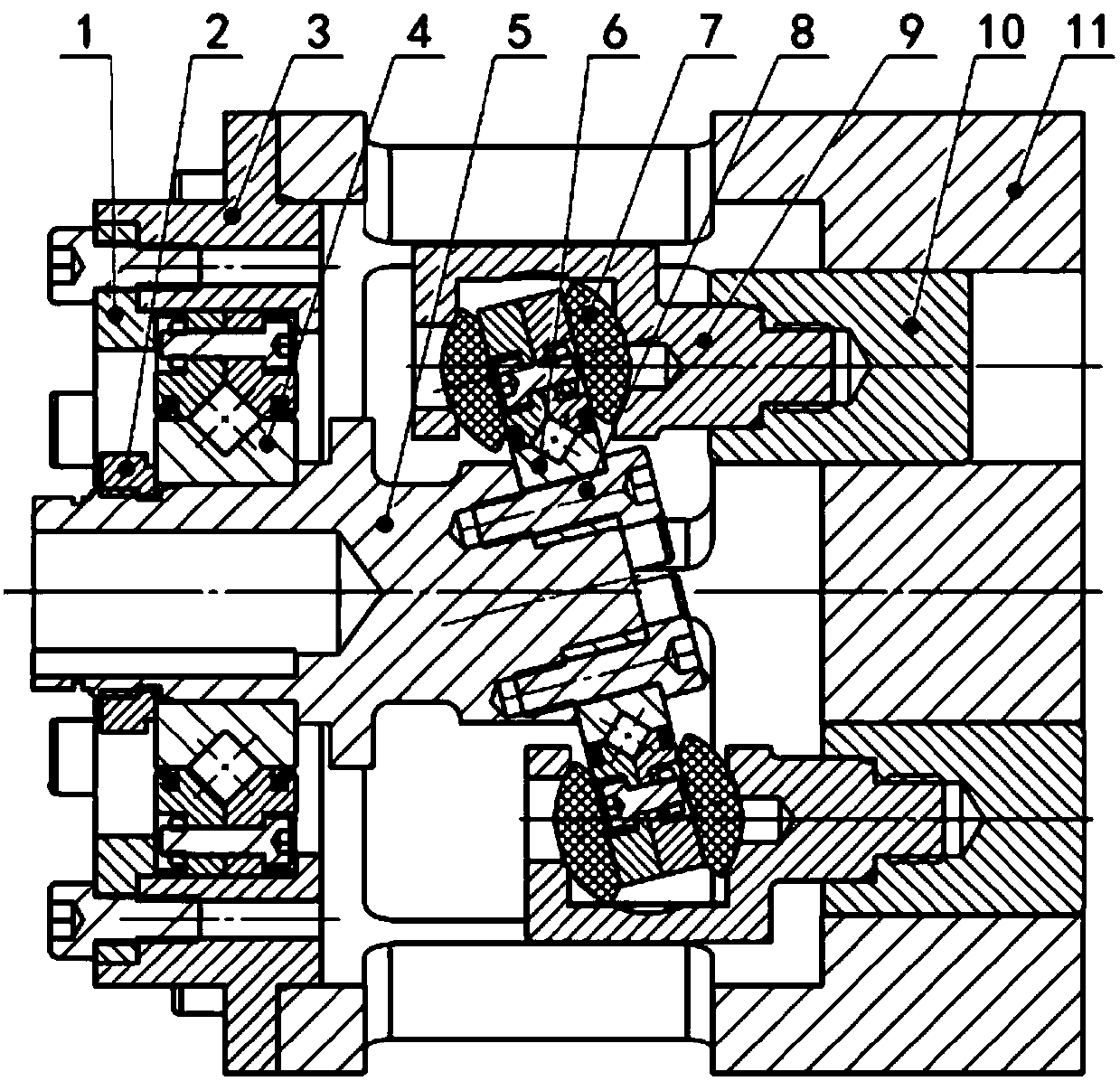
[0027] Such as figure 1 As shown, an embodiment of the present invention provides a driving mechanism for a reciprocating compressor. The driving mechanism belongs to the driving mechanism of an oil-free swash plate compressor. It includes a front end cover 3, a cylinder 11, a main shaft assembly, and a swash plate. Components and compression components, where the front end cover 3 is installed on the...


PUM


Abstract

The invention belongs to the field of universal mechanical compressors and discloses a reciprocating compressor driving mechanism. The driving mechanism comprises a front end cover, a cylinder block,a spindle assembly, a swash plate assembly and a compression assembly. The front end cover is mounted at the left end of the cylinder block. The spindle assembly comprises a spindle. The left end of the spindle is rotatably mounted on the front end cover through a crossed roller bearing. The swash plate assembly comprises a split swash plate fixed to the right end of the spindle. One part of the split swash plate is driven by the spindle to rotate relative to the other part, and the other part of the split swash plate only swings in the axial direction of the spindle. The compression assemblycomprises two compression units arranged up and down. Each compression unit comprises a return block and a piston which are connected. The return blocks make contact with the surface of the split swash plate through hemispherical hinges. The pistons are inserted into holes formed in the cylinder block. Through the reciprocating compressor driving mechanism, the problems that the friction coefficient of a sliding friction pair is high and the wearing capacity of the sliding friction pair is large under poor lubrication effect and lubrication-free conditions can be solved. The reciprocating compressor driving mechanism has the advantages of being small in friction coefficient, good in self-lubrication, small in heat yield and slow in temperature rising.

Description

Technical field [0001] The invention belongs to the field of general mechanical compressors, and more specifically, relates to a driving mechanism of a reciprocating compressor. Background technique [0002] Compressors are widely used in the national economy and national defense construction, especially in petroleum, chemical, power and other industrial fields have become indispensable key equipment. The traditional reciprocating compressor drive mechanism is a crank connecting rod mechanism, which has a large volume and a large reciprocating inertia force, which cannot achieve small size, light weight and high speed. [0003] With further development, swash plate compressors appeared. At present, swash plate compressors adopt an integral swash plate structure, such as CN107642476A, CN103195688A, etc. The entire swash plate rotates with the main shaft, and thus exists between the plane of the spherical joint Severe sliding friction, only in the case of good lubrication conditions...

Claims


Application Information

Patent Timeline
Patent Type & Authority Patents(China)
IPC IPC(8): F04B27/12F04B39/00F16C35/12
CPCF04B27/086F04B27/1063F04B27/12F16C35/12F16C2360/42
Inventor 邓亦攀刘银水吴德发苗娜庞浩
Owner HUAZHONG UNIV OF SCI & TECH
Why Eureka
Try Eureka