Spring and damper integrated shock absorber
An integrated damper technology, applied in the direction of spring/shock absorber, shock absorber, spring, etc., can solve the problems of difficult adjustment of spring, high cost of implementation, complex structure, etc., to achieve increased space and stable shock absorber , The effect of reducing the installation space
- Summary
- Abstract
- Description
- Claims
- Application Information
AI Technical Summary
Problems solved by technology
Method used
Image

Examples
Embodiment Construction
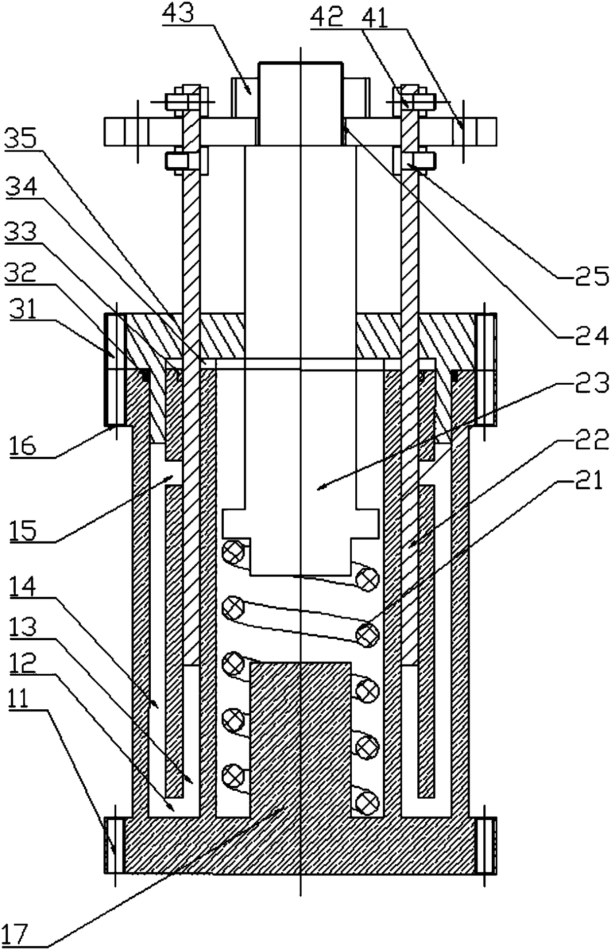
[0024] Embodiment of the present invention: spring and damper integrated shock absorber, as attached Figure 1-5 As shown, it includes four parts: a hydraulic damping device 1, a moving rod 2, a sealing device 3 and a connecting flange 4.
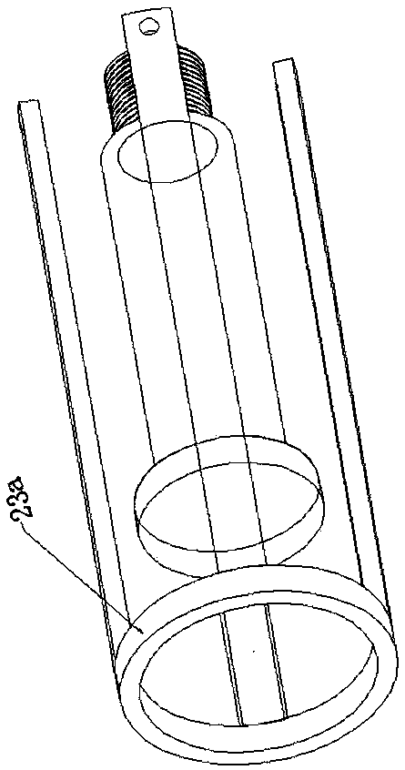
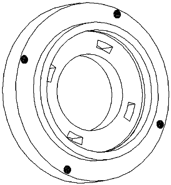
[0025] The hydraulic damping device 1 is an integrated cylindrical chamber composed of a lower threaded hole 11, an upper threaded hole 16, a lower throttle hole 12, an upper throttle hole 15, a right hydraulic chamber 13, a left hydraulic chamber 14, and a spring guide block 17; The moving rod 2 includes a spring 21, a No. 1 rod 22, a No. 2 rod 23, a threaded rod 24, and a through hole 25; the sealing device 3 is sealed by a threaded hole 31, a left hydraulic chamber sealing ring 32, and a right hydraulic chamber. Ring 33, moving rod sealing ring 34, and upper cover plate 35; the connecting flange 4 is composed of a vibration source connecting hole 41, a No. 1 rod fixing hole 42 and a threaded cap 43.
[0026] The hydraulic damping device...
PUM
 Abstract
Description
Claims
Application Information
 - Generate Ideas
- Intellectual Property
- Life Sciences
- Materials
- Tech Scout
- Unparalleled Data Quality
- Higher Quality Content
- 60% Fewer Hallucinations
Browse by: Latest US Patents, China's latest patents, Technical Efficacy Thesaurus, Application Domain, Technology Topic, Popular Technical Reports.
© 2025 PatSnap. All rights reserved.Legal|Privacy policy|Modern Slavery Act Transparency Statement|Sitemap|About US| Contact US: help@patsnap.com