Lip-shaped mechanical seal device

A mechanical sealing device and lip-shaped technology, which is applied in the direction of engine sealing, mechanical equipment, engine components, etc., can solve the problems of service life not meeting customer requirements, damage to the structure of the sealing ring, thermal deformation of the seal, etc., and achieve frictional heat energy Reduce, improve sealing performance, reduce the effect of frictional heat

Inactive Publication Date: 2018-08-17
苏州科耐迈克低温装备科技有限公司
View PDF0 Cites 1 Cited by
  • Summary
  • Abstract
  • Description
  • Claims
  • Application Information

AI Technical Summary

Problems solved by technology

However, there are still many problems in the mechanical seal at present. Once the mechanical moving ring and the static ring are in too tight contact, the sealing surface of the sealing ring will be worn during the rotation process, which will destroy the structure of the sealing ring, thereby destroying the seal as a whole. In addi

Method used


Image

  • Lip-shaped mechanical seal device
  • Lip-shaped mechanical seal device
  • Lip-shaped mechanical seal device

Examples


Example Embodiment

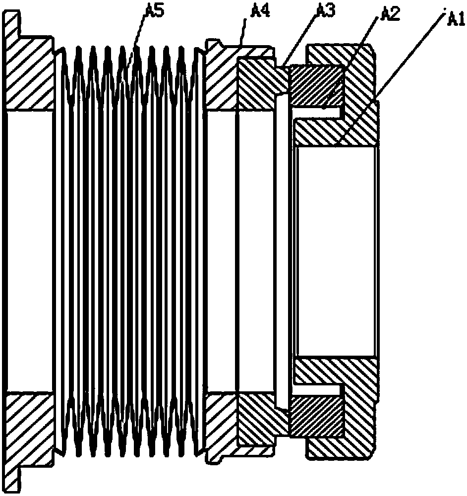
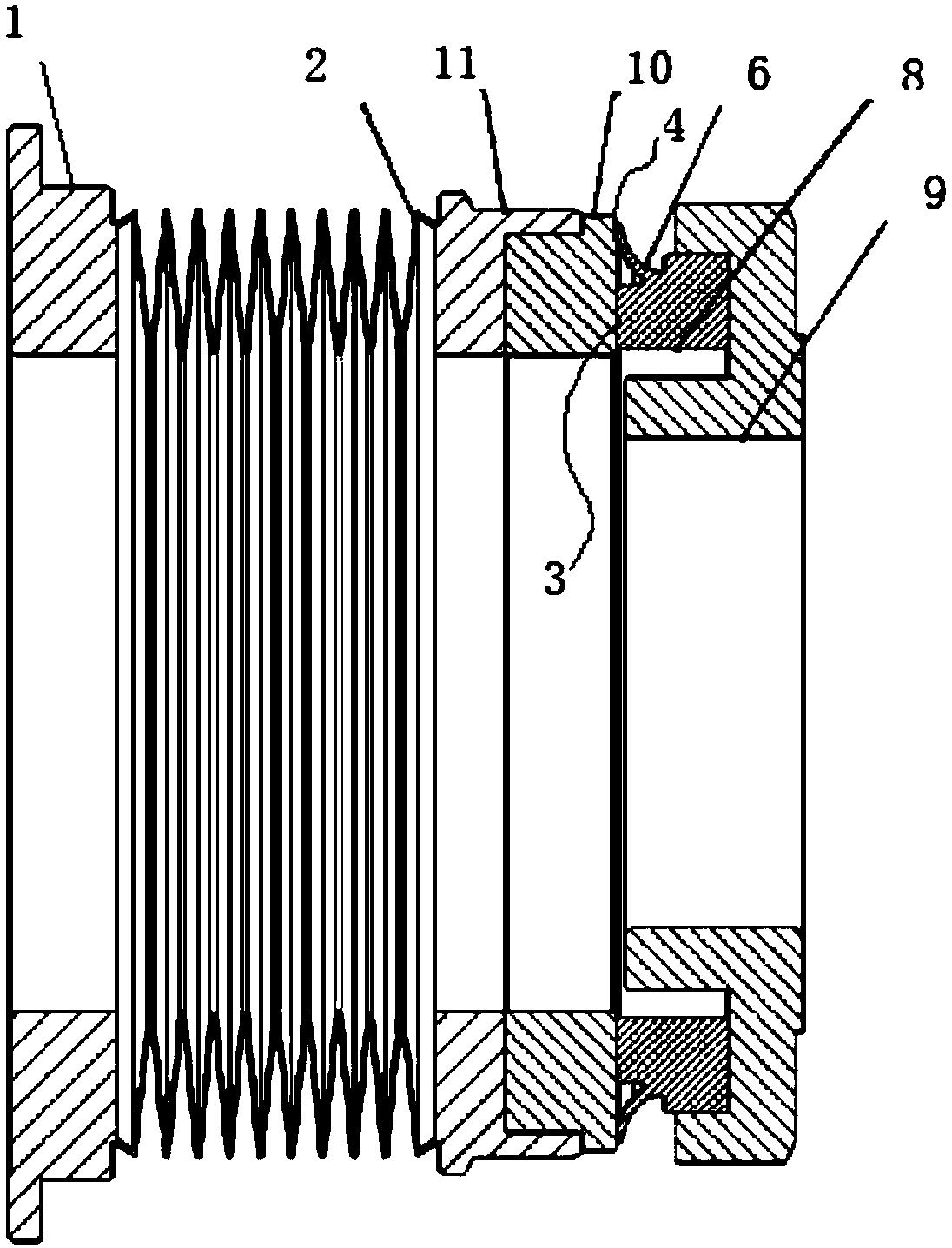
[0053] Embodiment 1: In this embodiment, as Figure 1 to Figure 3 As shown, the end surface of the movable ring has an end surface sealing lip, and the convex surface of the end surface sealing lip abuts against the end surface of the static ring to form the lip-shaped end surface seal.

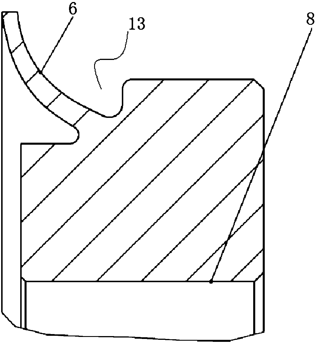
[0054] Such as image 3 As shown, the convex surface of the end face sealing lip is provided with a plurality of pumping grooves 12 for pressure reduction;

[0055] And / or the convex surface of the outer peripheral surface sealing lip is provided with a plurality of the pumping grooves 12 for pressure reduction.

[0056] The moving ring and the moving ring seat are integrally connected or separated.

[0057] When the static ring has an end face sealing lip or / and an outer peripheral face sealing lip, the static ring is a PTFE ring; the end face sealing lip or / and the outer peripheral face sealing lip are integrally connected with the static ring;

[0058] When the moving ring has an end face sealing li...

Example Embodiment

[0061] Embodiment 2: A lip-shaped mechanical seal device, the structure is similar to embodiment 1, the difference lies in: Figure 4 to Figure 5 As shown, the outer circumferential surface of the movable ring has an outer circumferential surface sealing lip, and the convex surface of the outer circumferential surface sealing lip abuts against the outer circumferential surface of the stationary ring seat to form the lip-shaped outer circumferential surface seal.

Example Embodiment

[0062] Embodiment 3: A lip-shaped mechanical seal device, the structure is similar to the embodiment, the difference lies in: Figure 6 to Figure 7 As shown, the end surface of the moving ring has an end surface sealing lip, the convex surface of the end surface sealing lip abuts against the end surface of the static ring to form the lip-shaped end surface seal, and the outer peripheral surface of the moving ring has an outer peripheral surface A sealing lip, the convex surface of the sealing lip of the outer peripheral surface and the outer peripheral surface of the stationary ring seat abut to form the lip-shaped outer peripheral surface seal.

[0063] In this embodiment, the moving ring is split, that is, it is composed of two sub-moving rings, one of which has an end face sealing lip, and the other has an outer peripheral face sealing lip.


PUM


Abstract

The invention discloses a lip-shaped mechanical seal device. The lip-shaped mechanical seal device comprises a mounting base, a compensation element and two cup bodies. The two cup bodies comprise thefixed cup body and the moveable cup body. Flat end face seal is formed between the two contact end faces of the fixed cup body and the movable cup body. At least one of lip-shaped end face seal and lip-shaped outer circumferential face seal is further formed between the two cup bodies. An end face sealing lip abuts against the end faces of the cup bodies to form lip-shaped end face seal. An outercircumferential face sealing lip abuts against the outer circumferential faces of the cup bodies to form lip-shaped outer circumferential face seal. The lip-shaped seal structure mode is adopted, inaddition, a pumping groove is formed in a lip, leaking media are pumped back reversely, and the sealing effect is enhanced; and in addition, friction heat between sealing end faces is realty reduced by adopting a PTFE material, abrasion of the sealing end faces is reduced, and the situation that the end faces are opened and leakage and collision damage occur due to temperature rising and medium gasifying is prevented.

Description

technical field [0001] The invention relates to the technical field of mechanical seals, in particular to a mechanical seal device, which is mainly used in rotating machines, such as various pumps, compressors and reactors. Background technique [0002] Mechanical seal (mechanical seal) refers to at least one pair of end faces perpendicular to the axis of rotation, under the action of fluid pressure and the elastic force (or magnetic force) of the compensation mechanism, and the cooperation of the auxiliary seal to keep fit and relatively slide to prevent fluid leakage. device. [0003] Mechanical seals are widely used in petroleum, chemical, mechanical and aerospace fields. Mainly used in rotating machinery, the function of the seal is to prevent the leakage of the sealed medium, and at the same time prevent external pollutants and impurities from entering the equipment cavity, thereby polluting the medium in the equipment cavity. [0004] Currently commonly used mechanic...

Claims


Application Information

Patent Timeline
IPC IPC(8): F16J15/3204F16J15/3244F16J15/3284F16J15/34
CPCF16J15/3204F16J15/3244F16J15/3284F16J15/3436F16J15/3452F16J15/3464F16J15/3496
Inventor 刘鑫张岳林刘广辉刘永志李定
Owner 苏州科耐迈克低温装备科技有限公司
Why Eureka
Try Eureka