
Space target transit area position detecting method and system

A technology of space target and detection method, applied in measurement devices, instruments, etc., can solve the problems of low speed and efficiency of position determination, high calculation and performance requirements, and large amount of redundant calculation, so as to reduce useless calculation and improve calculation. The effect of efficiency and speed

Active Publication Date: 2018-08-17
PLA STRATEGIC SUPPORT FORCE INFORMATION ENG UNIV PLA SSF IEU
View PDF5 Cites 2 Cited by
  • Summary
  • Abstract
  • Description
  • Claims
  • Application Information

AI Technical Summary

Problems solved by technology

[0005] The object of the present invention is to provide a method and system for detecting the position of a space object transit area, which is used to solve the problem of large amount of redundant calculation and low speed and efficiency of position determination in the traditional space object position detection method for space object transit area. The problem of high performance requirements

Method used


Image

  • Space target transit area position detecting method and system
  • Space target transit area position detecting method and system
  • Space target transit area position detecting method and system

Examples


Embodiment 1

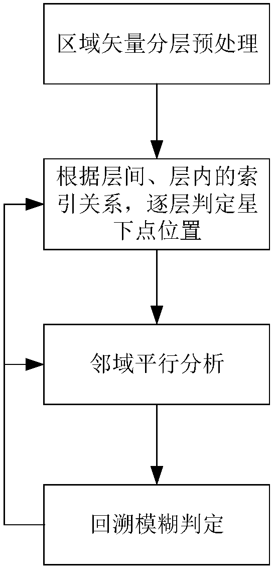
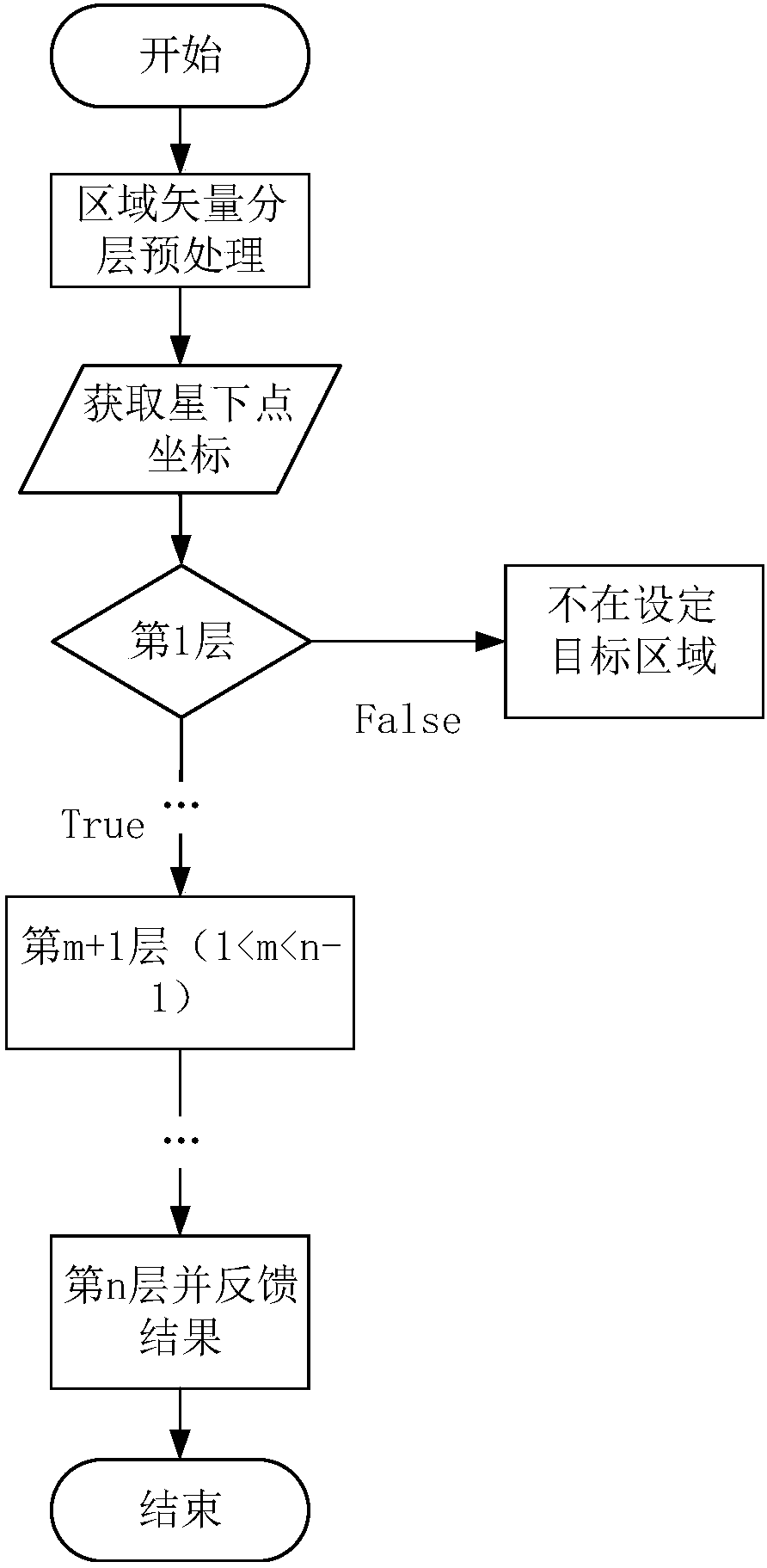
[0042] Embodiment 1 provides a method for detecting the downward point position of a spatial object, such as image 3 As shown, after the preprocessing based on the vector layering, the latitude and longitude coordinates of the sub-satellite point of the space target are obtained through the existing means.

[0043] Step 1: Calculate the spatial position relationship between the sub-satellite point and the vector map of the first layer, judge whether it is in the first layer, if the result is true, proceed to the next step, otherwise output the result, the spatial object is not in the set target area.

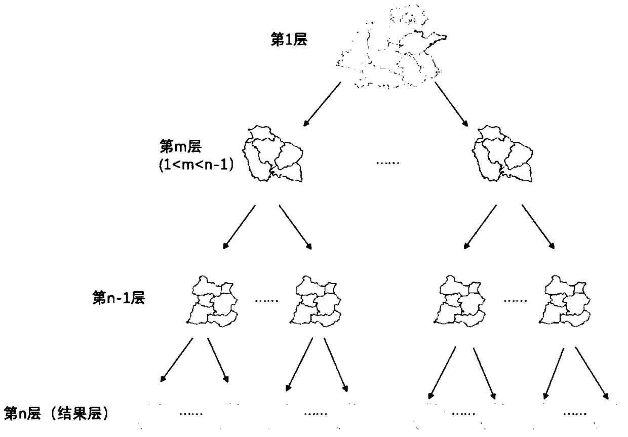
[0044] Gradually increase the vector level and narrow the target area according to the index relationship established between the levels.

[0045] Step 2: Calculate the sub-satellite point and the m+1th layer (1<m<n-1) vector map in sequence for spatial position relationship, record and obtain the results, and continue to calculate and judge higher levels.

[0046] Step 3: Whe...

Embodiment 2

[0049] Satellites are highly dynamic, and their monitoring is also real-time and high-frequency. However, although the above-mentioned layered thinking can reduce a large number of redundant calculations in the calculation process of the sub-satellite point position, each time the satellite is calculated The position of the next point needs to repeat the whole process, so the method in Embodiment 1 does not solve the redundant calculation problem in the continuous monitoring process.

[0050] Constrained by orbital dynamics, a space object moves in an ellipse with the earth as its focus. Although its absolute position changes rapidly with time, its orbit remains relatively stable in inertial space for a certain period of time. Therefore, on the basis of layering, based on orbital constraints, a calculation scheme suitable for the continuous and rapid judgment of the position of the sub-satellite point of the space target is obtained. This embodiment 2 is carried out on the basi...


PUM


Abstract

The present invention relates to the technical field of space target location monitoring and more particularly relates to a space target transit area position detection method and system. The system comprises a memory, a processor and a computer program which is stored in the memory and can run in the processor. When the processor executes the program, the acquisition of latitude and longitude coordinates of a sub-satellite point of a space target is achieved. A set target area vector diagram is divided into n layers, the index relationship between layers and the index relationship in a layerare established, and a target range is smaller as a layer increases. When sub-satellite point is in a first layer, the space position relationship judgment of the sub-satellite point and a (m+1)th layer vector diagram is carried out, m is larger than 1 and is smaller than n-1, the calculation and judgment are further carried out on a higher layer until a judgment layer is accurate to the nth layer, the first-time determination of the position of the sub-satellite point is realized quickly by layer-by-layer downward analysis, and the problem that a redundancy calculation amount is larger and speed and efficiency of position judgment are low in a traditional space target transit area position detection method and thus the requirements for calculation and performance are high is solved.

Description

technical field [0001] The invention relates to the technical field of space target position monitoring, in particular to a method and system for detecting the position of a space target transit area. Background technique [0002] In recent years, with the development of science and technology and the improvement of social needs, countries around the world have launched a large number of spacecraft to serve human life, scientific research and military fields. As we all know, satellites run extremely fast, have a large number, and require high real-time performance. Therefore, when performing work such as transit window calculation, early warning analysis, and coverage analysis on them, they will face a huge amount of calculation. Real-time transit monitoring of satellites flying at high speed in space has become an urgent need for the aerospace sector and related application sectors. [0003] The real-time transit monitoring of satellites is a cumbersome and computationally...

Claims


Application Information

Patent Timeline
IPC IPC(8): G01B21/00
CPCG01B21/00
Inventor 施群山徐青赵英豪蓝朝桢吕亮卢万杰周扬邢帅张衡张永显
Owner PLA STRATEGIC SUPPORT FORCE INFORMATION ENG UNIV PLA SSF IEU
Learn More