Vehicle high-temperature temperature sensor thermal response test method

A technology of temperature sensor and thermal response test, applied in the field of sensor detection

Inactive Publication Date: 2018-08-17
山西润玖汽车配件科技有限公司
View PDF4 Cites 5 Cited by
  • Summary
  • Abstract
  • Description
  • Claims
  • Application Information

AI Technical Summary

Problems solved by technology

[0003] The traditional temperature sensor thermal response test can only test the bare product in which the temperature sensitive medium is directly in contact with the measured medium

Method used


Image

  • Vehicle high-temperature temperature sensor thermal response test method
  • Vehicle high-temperature temperature sensor thermal response test method
  • Vehicle high-temperature temperature sensor thermal response test method

Examples


Embodiment Construction

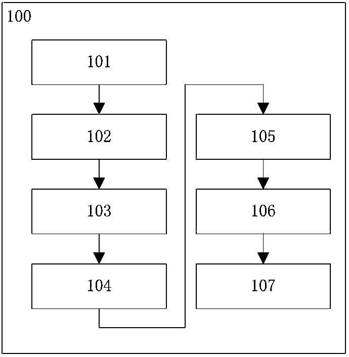
[0038] figure 1A flow chart of a thermal response testing method 100 for a vehicle high-temperature temperature sensor proposed according to the present invention is shown. The method comprises the following steps: setting the constant temperature source to a predetermined temperature T t 101; place the temperature sensor to be tested at room temperature T s Under the environment and continue for a specific time 102; the temperature sensor to be measured is connected with the measuring device and records the current room temperature T s =T O 103; Calculate step temperature T n and timed temperature T x 104; put the sensor to be tested into the constant temperature source and set it as the initial time t 0 105; respectively record each timing time t when the sensor to be tested reaches the timing temperature x 106; Calculate the timing time t x with initial time t 0 interval t x -t 0 107.

[0039] The method for testing the thermal response of a high-temperature tem...


PUM


Abstract

The present invention relates to a vehicle high-temperature temperature sensor thermal response test method (100). The method comprises the following steps of: setting a constant temperature source toa preset temperature Tt (101); putting a temperature sensor to be measured into an environment at a room temperature Ts for special time (102); connecting the temperature sensor to be measured with ameasurement device, and recording a current room temperature Ts=T0 (103); calculating a step change temperature Tn and a timing temperature Tx (104); putting the sensor to be measured into the constant temperature source, and setting initial time t0 (105); recording each timing time tx (106) when the sensor to be measured reaches the timing temperature; and calculating an interval tx-t0 (107) ofthe timing time tx and the initial time t0.

Description

technical field [0001] The invention relates to sensor detection technology, in particular to a thermal response test method of a high-temperature temperature sensor for vehicles. Background technique [0002] Currently, there are many thermal response time testing methods for temperature sensors. The most commonly used and easiest method is the input experiment method, that is, the temperature sensor with known static characteristics is placed in a gas or liquid medium with a certain temperature and is stable, and it is connected to the sensor test circuit. Then use the temperature response time test software in the computer to measure the initial value of the temperature sensor, and set the sampling time, sampling frequency, trigger level and other parameters in the test interface. At the same time, set the temperature of the constant temperature source to an integer value higher than the initial temperature and lower than the upper limit temperature of the temperature se...

Claims


Application Information

Patent Timeline
Patent Type & Authority Applications(China)
IPC IPC(8): G01K15/00
CPCG01K15/007
Inventor 徐俊王磊王星
Owner 山西润玖汽车配件科技有限公司
Why Eureka
Try Eureka