State of charge calibration method and device for energy storage system

A state-of-charge, energy storage system technology, applied in the field of energy storage, can solve problems such as inconsistent current sampling accuracy, poor user friendliness, and difference in charging and discharging currents, achieve reasonable energy management and power prediction, and improve SOC consistency. Effect

Active Publication Date: 2019-10-29
CONTEMPORARY AMPEREX RUNZHI SOFTWARE TECH LTD NINGDE CITY
View PDF8 Cites 0 Cited by
  • Summary
  • Abstract
  • Description
  • Claims
  • Application Information

AI Technical Summary

Problems solved by technology

Since the cell impedance between the parallel cabinets in the system cannot be completely consistent, this leads to a certain difference in the charging and discharging current between the system cabinets during charging and discharging.
The current difference between the cabinets and the current sampling accuracy between each cabinet are not consistent, which eventually leads to a certain deviation in the calculated SOC value between each cabinet, and as time continues to prolong, the deviation will be continuously The SOC deviation between the parallel cabinets of the system will become larger and larger
At present, it is mainly used to solve the method of large SOC deviation between parallel cabinets. The average value calibration method can calibrate the SOC of all cabinets to the average value of all cabinets during calibration. However, the calibrated value is different from that of the battery. The actual capacity error may be relatively large, and the SOC of the cabinet will reappear inconsistent with the charging and discharging of the system after calibration, which is not conducive to the energy management and power prediction of the system, and the user friendliness is relatively poor

Method used


Image

  • State of charge calibration method and device for energy storage system
  • State of charge calibration method and device for energy storage system
  • State of charge calibration method and device for energy storage system

Examples


Embodiment Construction

[0048] In order to make the purpose of the invention, the technical solution and its beneficial technical effects clearer, the present invention will be further described in detail below in conjunction with the accompanying drawings and specific embodiments. It should be understood that the specific implementations described in this specification are only for explaining the present invention, not for limiting the present invention.

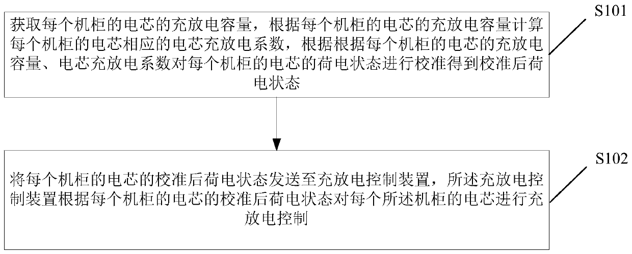
[0049] see figure 1 , a work flow diagram of a method for calibrating the state of charge of an energy storage system in the present invention, the energy storage system includes a plurality of parallel cabinets accommodating batteries, including:

[0050] Step S101, including: obtaining the charging and discharging capacity of the batteries in each cabinet, calculating the corresponding charging and discharging coefficient of the batteries in each cabinet according to the charging and discharging capacity of the batteries in each cabinet, The ch...


PUM


Abstract

A method for calibrating a state of charge of an energy storage system, the energy storage system comprising a plurality of machine cabinets which are connected in parallel and which accommodate battery cores. The method comprises: acquiring a charge and discharge capacity of a battery core of each machine cabinet, calculating a battery core charge and discharge coefficient corresponding to the battery core of each machine cabinet according to the charge and discharge capacity of the battery core of each machine cabinet, and according to the charge and discharge capacity and the battery core charge and discharge coefficient of the battery core of each machine cabinet, then calibrating a state of charge of the battery core of each machine cabinet to obtain a calibrated state of charge (S101); sending the calibrated state of charge of the battery core of each machine cabinet to a charge and discharge control device, the charge and discharge control device performing charge and discharge control on the battery core of each machine cabinet according to the calibrated state of charge of the battery core of each machine cabinet (S102). A battery core charge and discharge coefficient Kx is added during a process of the energy saving system performing state of charge (SOC) calculation to perform calibration, which may improve SOC consistency between machine cabinets which are connected in parallel in the system.

Description

technical field [0001] The invention belongs to the technical field of energy storage, and more specifically, the invention relates to a method and a device for calibrating the state of charge of an energy storage system. Background technique [0002] Large-scale energy storage systems are considered to play an integral and important role in supporting the spread of renewable energy sources such as wind and solar. With the rapid development of wind power, photovoltaic and other renewable energy power generation and smart grid industries, large-scale energy storage systems have become the focus of much attention. With the continuous use of large-scale energy storage systems, the problems of inaccurate calculation of its state of charge (State of Charge, SOC) and relatively large SOC deviation between cabinets have been exposed. [0003] The existing SOC estimation methods have the following problems: [0004] The main SOC estimation method currently used is the ampere-hour ...

Claims


Application Information

Patent Timeline
Patent Type & Authority Patents(China)
IPC IPC(8): G01R31/388G01R31/3835
CPCG01R31/382G01R31/387G01R31/36
Inventor 鲍芳斌岳洪亮魏志立
Owner CONTEMPORARY AMPEREX RUNZHI SOFTWARE TECH LTD NINGDE CITY
Why Eureka
Try Eureka