
Skylight shading component

A component and sunroof technology, applied to vehicle components, roofs, transportation and packaging, etc., can solve problems such as poor fastening strength, difficulty in maintaining consistent elastic force values, and inability to effectively limit the elastic deformation of metal shrapnel 22, so as to avoid tilting , to avoid the effect of deformation difference

Pending Publication Date: 2018-08-21
SHANGHAI INTEVA AUTOMOTIVE PARTS
View PDF0 Cites 0 Cited by
  • Summary
  • Abstract
  • Description
  • Claims
  • Application Information

AI Technical Summary

Problems solved by technology

[0004] 1. The material cost of the shading component body 1 is high; the material density of the shading component body 1 is high, and steel bars 13 are embedded, see image 3 As shown; the mass of the assembly parts is large, 1170g, the material is hard PU, and the material cost is high
[0005] 2. The energy-absorbing effect of the limit buffer 3 is poor; the limit buffer 3 of the shading component has no buffer and energy-absorbing structure, resulting in poor energy-absorbing effect, see Figure 4 shown
[0006] 3. The shading assembly has a large sliding force in the guide rail, has a strong sense of blockage, and causes customer dissatisfaction; the existing shading assembly has 4 metal shrapnel sliders, and the middle parts of the metal shrapnel 22 of the 4 sliders 2 are directly connected to the shading assembly body. 1 Fixed connection, the two legs of the metal shrapnel 22 extend into the guide rail, and the plastic contact parts 23 in contact with the guide rail are installed on the two legs, the elastic deformation of the metal shrapnel 22 in the front-back direction and the up-down direction cannot be obtained Effective restriction, and the elastic force values ​​of the metal domes 22 of the four sliders 2 are difficult to keep consistent, so the deformation values ​​of the metal domes 22 of the four sliders 2 have a large difference, and the sliding force fluctuates greatly when the shading component runs in the guide rail , and reach 15N-30N, and cause the operating state of the shading component to be unstable, see Figure 5 shown
[0007] 4. The size of the handle 41 is large, the structure is complex and the materials used are many, its weight, quality, and mold cost are high, see Image 6 shown
[0008] 5. The fastening strength between the handle 41 and the slider 2 and the shading assembly body 1 is poor; poor

Method used


Image

  • Skylight shading component
  • Skylight shading component
  • Skylight shading component

Examples


Embodiment Construction

[0071] The implementation of the present invention will be illustrated by specific specific examples below, and those skilled in the art can easily understand other advantages and effects of the present invention from the contents disclosed in this specification.

[0072] It should be noted that the structures, proportions, sizes, etc. shown in the drawings of this specification are only used to match the content disclosed in the specification, for those who are familiar with this technology to understand and read, and are not used to limit the conditions for the implementation of the present invention , so it has no technical substantive meaning, and any modification of structure, change of proportional relationship or adjustment of size shall still fall within the scope of the disclosure of the present invention without affecting the functions and objectives of the present invention. within the range covered by the technical content. At the same time, terms such as "upper", ...


PUM


Abstract

The invention provides a skylight shading component. The skylight shading component comprises a shading component body, multiple sliders, a limiting buffer and a handle, wherein the sliders comprise slider bodies installed on the shading component body and metal elastic pieces installed in the slider bodies, the slider bodies are provided with sliding contact parts which are internally provided with clamping grooves, the metal elastic pieces are embedded in the clamping grooves, the sliding contact parts are used for being embedded in a guide groove of a guide rail. In the invention, as the metal elastic pieces are embedded in the clamping grooves of the sliding contact parts, during use, the sliding contact parts are embedded in the guide groove so as to utilize the guide groove to limitthe deformation quantity of the metal elastic pieces along an up-down direction, the deformation quantity of the metal elastic pieces is effectively limited, so that relatively great deformation differences along the up-down direction among the multiple sliders are avoided, and then the skylight shading component can be guaranteed to stably operate along the guide groove and the guide rail.

Description

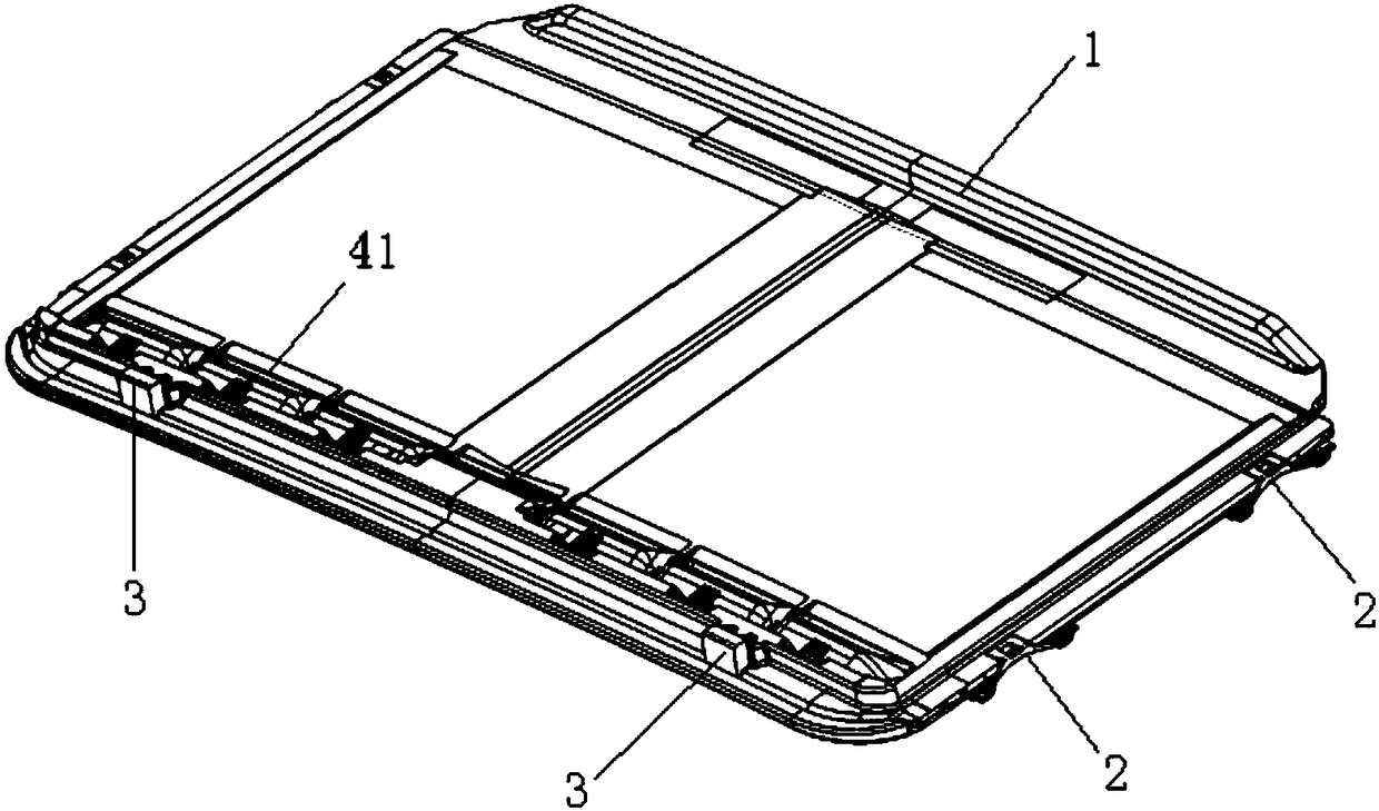
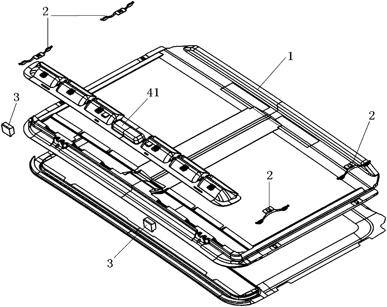
technical field [0001] The invention relates to the technical field of automobile manufacturing, in particular to a sunroof shading assembly. Background technique [0002] For the typical structural design of existing sunroof shading components, see figure 1 shown. At the same time, the production process of the existing sunroof shading assembly is as follows: first obtain the shading assembly body 1 by injection molding, then glue the cloth 8 on the shading assembly body 1, and assemble the handle 41 and the slider 2 with the shading assembly body 1, See figure 2 shown. [0003] The existing shading assembly has the following disadvantages: [0004] 1. The material cost of the shading component body 1 is high; the material density of the shading component body 1 is high, and steel bars 13 are embedded, see image 3 As shown; the mass of the assembly parts is large, 1170g, and its material is hard PU, and the material cost is high. [0005] 2. The energy-absorbing eff...

Claims


Application Information

Patent Timeline
Patent Type & Authority Applications(China)
IPC IPC(8): B60J7/00B60J7/02
CPCB60J7/00B60J7/02
Inventor 蔡飞翔常喜安王军强邱新胜
Owner SHANGHAI INTEVA AUTOMOTIVE PARTS
Learn More