
Automobile hub conveying device and conveying method thereof

A technology for conveying equipment and automobile hubs, applied in the field of automobile manufacturing, can solve problems such as hub damage, hubs cannot be placed uniformly for transportation, traffic accidents, etc.

Active Publication Date: 2018-08-21
ANHUI SANLIAN UNIV
View PDF4 Cites 4 Cited by
  • Summary
  • Abstract
  • Description
  • Claims
  • Application Information

AI Technical Summary

Problems solved by technology

There are many types of hubs according to diameter, width, molding method, and material. During the production and transportation of hubs, because the hubs are cylindrical in shape as a whole, it is not easy to fix them. At the same time, hubs with different diameters cannot be placed and transported uniformly. They must be placed separately, which increases the transportation. cost, and the collision between adjacent hubs during transportation causes damage to the hubs and affects the accuracy of the wheels. During the use of the car, the deviation of the wheels is likely to cause traffic accidents in rainy or snowy days

Method used


Image

  • Automobile hub conveying device and conveying method thereof
  • Automobile hub conveying device and conveying method thereof
  • Automobile hub conveying device and conveying method thereof

Examples


Embodiment Construction

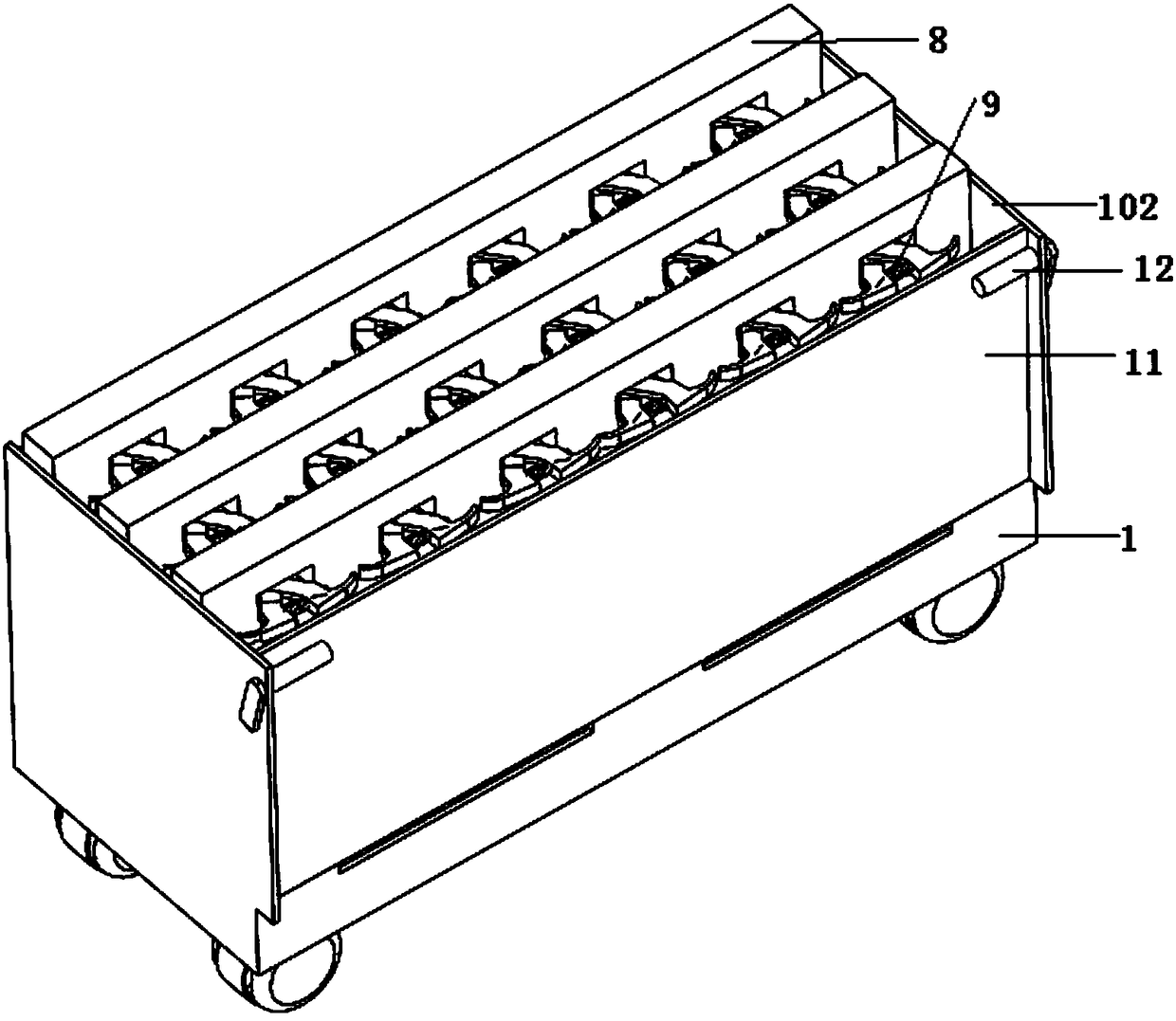
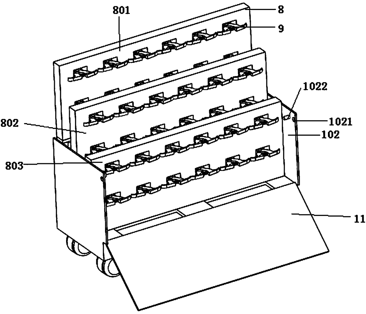
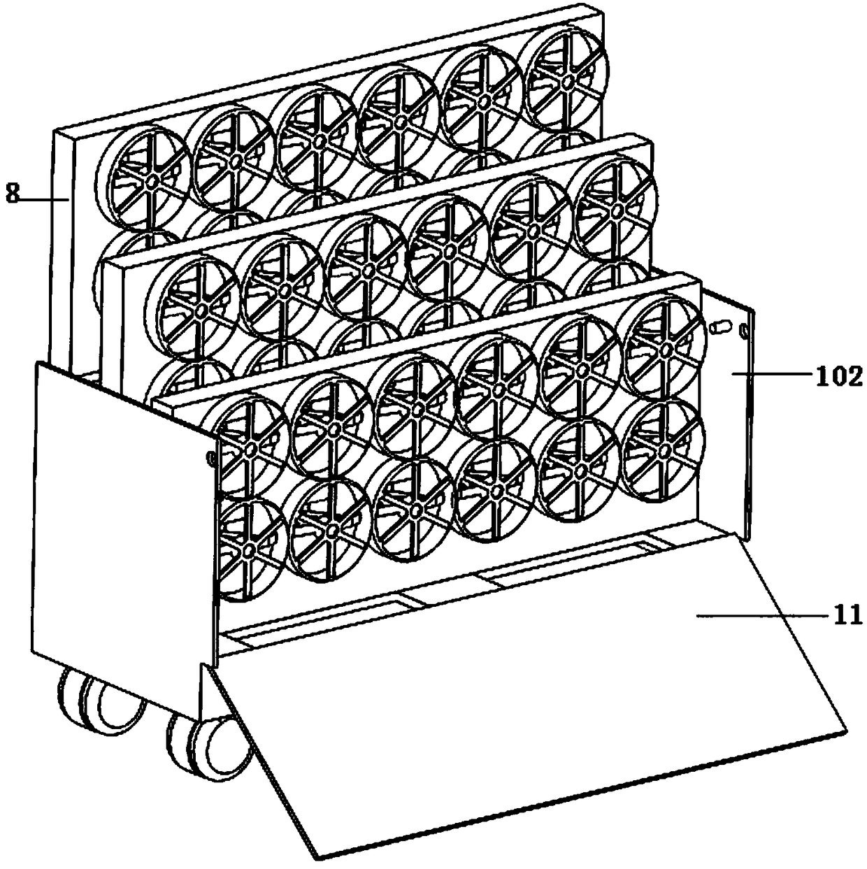
[0030] Automobile hub conveying equipment, such as figure 1 , figure 2 , image 3 As shown, the support box 1 is included, the four corners of the bottom surface of the support box 1 are fixed with several universal wheels, the top of the rear side wall of the support box 1 is fixed with a rear first baffle 101, and the top of the left and right side walls of the support box 1 Two second baffles 102 oppositely arranged are fixed;

[0031] Such as Figure 4 , Figure 5 with Figure 6 As shown, the center of the top surface of the front and rear side walls of the support box 1 is vertically fixed with a horizontally distributed first support plate 103, and the two sides of the front and rear side wall top surfaces of the support box 1 are vertically fixed with a horizontally distributed first support plate 103. Two support plates 104, the center of the rear side wall of the support box 1 is installed with a first rotating shaft, one end of the first rotating shaft is conne...


PUM


Abstract

The invention discloses an automobile hub conveying device. The automobile hub conveying device comprises a supporting box body; a first supporting plate and a second supporting plate are perpendicularly fixed to the top end surfaces of the side walls of the supporting box body; a first rotating shaft is fixed to the rear side wall of the supporting box body; a driving bevel gear is fixed to one end of the first rotating shaft; a second rotating shaft is installed and fixed to the surface of the first supporting plate; a driven bevel gear matched with the driving bevel gear is fixed to the bottom end of the second rotating shaft, and a first driven gear is fixed to the top end of the second rotating shaft; a first screw rod is fixed to the end face of the first driven gear; a first fixingshaft and a second fixing shaft are fixed to the surface of the first supporting plate; a second driven gear engaged with the first driven gear is fixed to the first fixing shaft; and a second screw rod is fixed to the end face of the second driven gear. The automobile hub conveying device is provided with a plurality of bearing plates, when the bearing plates are used, the bearing plates are madeto be in stair-shaped distribution due to transmission of the gears and the screw rods, the adjacent bearing plates are not affected by each other during hub taking and placing, and hubs on the upperlayer and the lower layer of the bearing plates can be directly taken and placed conveniently.

Description

technical field [0001] The invention belongs to the field of automobile manufacturing, and relates to an automobile hub conveying device and a conveying method thereof. Background technique [0002] The wheel hub is a barrel-shaped metal part whose center is mounted on the shaft, and is also called a rim, a steel ring, a wheel, and a tire bell. There are many types of hubs according to diameter, width, molding method, and material. During the production and transportation of hubs, since the hubs are cylindrical in shape as a whole, it is not easy to fix them. At the same time, hubs with different diameters cannot be placed and transported uniformly, but must be placed separately, which increases the transportation. cost, and the collision between adjacent hubs during transportation causes damage to the hubs and affects the accuracy of the wheels. During the use of the car, traffic accidents are likely to occur due to the deviation of the wheels in rainy or snowy days. Cont...

Claims


Application Information

Patent Timeline
Patent Type & Authority Applications(China)
IPC IPC(8): B65D25/24B65D25/10B65D25/02B65D85/02
CPCB65D25/02B65D25/10B65D25/24B65D85/02
Inventor 王艳梅唐志华吴芳芳李茹婷
Owner ANHUI SANLIAN UNIV
Learn More