Eureka AIR delivers breakthrough ideas for toughest innovation challenges, trusted by R&D personnel around the world.

Double-wall cooling and film cooling combined turbine blade structure

A technology of turbine blade and air film cooling, which is applied to the supporting elements of blades, engine elements, machines/engines, etc., can solve the problems of large consumption of cooling air, large flow resistance of double-walled structure, and cold air flow not going out, etc. To achieve the effect of optimizing the layout design

Pending Publication Date: 2018-08-21
INST OF ENGINEERING THERMOPHYSICS - CHINESE ACAD OF SCI
View PDF0 Cites 13 Cited by
  • Summary
  • Abstract
  • Description
  • Claims
  • Application Information

AI Technical Summary

Problems solved by technology

If a typical double wall is used directly for blade cooling, this will consume a large amount of cooling air
At the same time, the space at the leading edge of the turbine moving blade is narrow, the static pressure of the local mainstream is relatively large, and the flow resistance of the double-wall structure is relatively large. When the leading edge of the turbine blade is designed as a double-wall structure, there is a pressure difference caused by cold air. The problem of being too small to flow out

Method used


Image

  • Double-wall cooling and film cooling combined turbine blade structure
  • Double-wall cooling and film cooling combined turbine blade structure
  • Double-wall cooling and film cooling combined turbine blade structure

Examples


Embodiment Construction

[0022] In order to make the object, technical solution and advantages of the present invention clearer, the present invention will be further described in detail below with reference to the accompanying drawings and examples. It should be understood that the specific embodiments described here are only used to explain the present invention, not to limit the present invention. In addition, the technical features involved in the various embodiments of the present invention described below can be combined with each other as long as they do not constitute a conflict with each other.

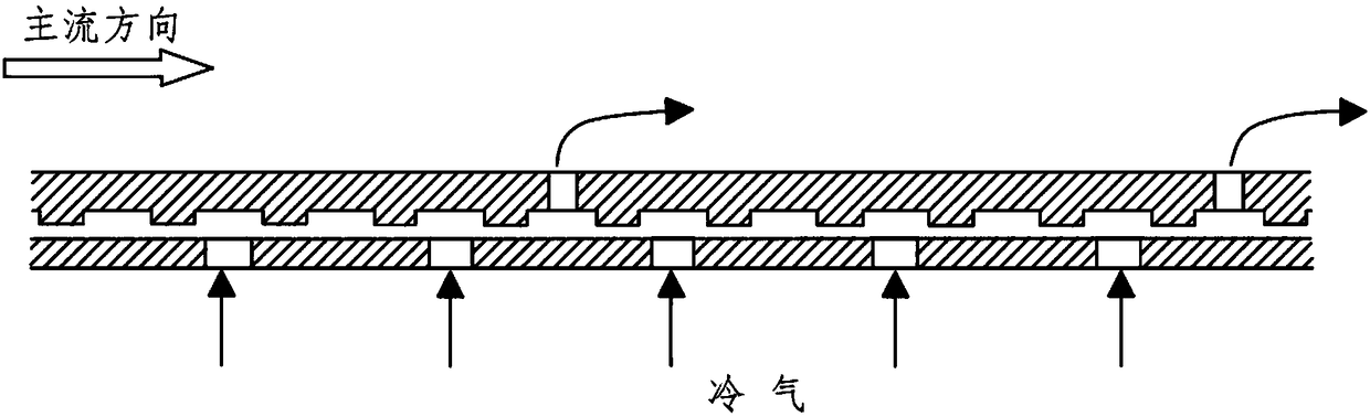
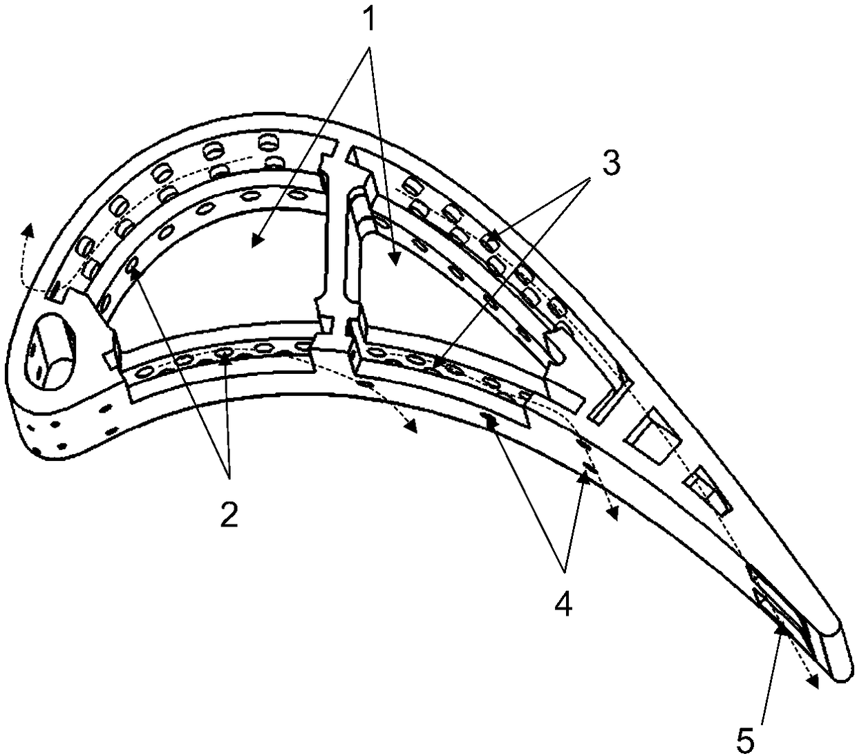
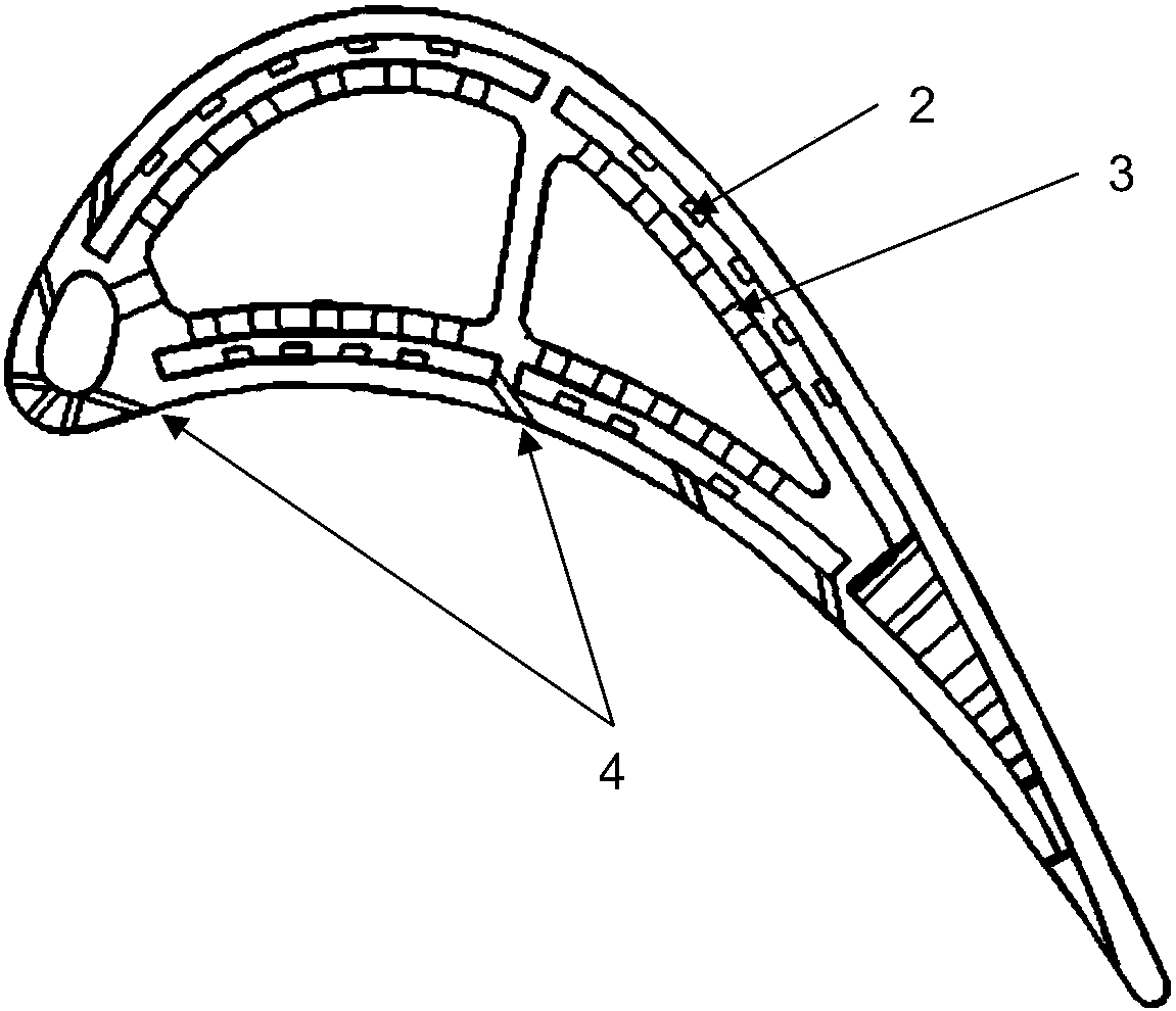
[0023] Such as figure 2 , 3 As shown, the combined double-wall cooling and film cooling turbine blade structure of the present invention includes a film cooling structure at the leading edge of the blade and a double-wall cooling structure on the main body of the airfoil. A cold air passage extending along the span direction of the blade is provided in the leading edge area of ​​the blade, and air...


PUM


Abstract

The invention provides a double-wall cooling and film cooling combined turbine blade structure, and relates to the gas turbine blade cooling technology. The combined turbine blade structure is used for cooling gas turbine blades. The structure comprises a film cooling structure located at the leading edge of a blade, and a double-wall cooling structure located on a blade body. The combined turbineblade structure is different from a conventional blade in that the ribbed channel structure of the blade body is converted into the double-wall cooling structure, and the double wall of the double-wall cooling structure is composed of impact openings, turbulence columns and film holes; the turbulence columns are designed into lateral half-height turbulence columns, and the flow resistance coefficient can be reduced. Since the double-wall cooling structure has the good impact cooling effect that the ribbed channel structure does not have, the combined turbine blade structure has the advantagesof higher comprehensive cooling effect, and lower wall temperature and longer service life of the turbine blade under the same cold air conditions.

Description

technical field [0001] The invention belongs to the technical field of gas turbine blade cooling, and relates to a double-wall cooling and film cooling combined turbine blade structure, in particular to a blade whose front edge adopts traditional air film cooling and blade body adopts a new type of double-wall cooling The cooling structure is used in the structural design of the gas turbine blades, which can obviously improve the cooling efficiency of the gas turbine blades. Background technique [0002] At present, the gas turbine generally adopts a composite cooling method of complex multi-channel forced convection air-entrained film cooling, which can reduce the average temperature of the blade metal by 500-700K, and the cooling efficiency is 0.5-0.6. In the future, the turbine inlet temperature of the gas turbine will reach 1973K. In order to meet the requirements of further increase in the turbine inlet temperature of the gas turbine in the future, cooling technology is...

Claims


Application Information

Patent Timeline
IPC IPC(8): F01D5/18
CPCF01D5/18F01D5/186F05D2260/201
Inventor 张晓东安柏涛曾蕴涛林晓春
Owner INST OF ENGINEERING THERMOPHYSICS - CHINESE ACAD OF SCI
Why Eureka
Eureka Blog
Learn More