Eureka AIR delivers breakthrough ideas for toughest innovation challenges, trusted by R&D personnel around the world.

Electronic atomization device and control circuit and method thereof

An electronic atomization device and control circuit technology, applied in electrical components, tobacco and other directions, can solve the problems of low reliability, many leads, and high production costs, and achieve the effects of reducing production costs, optimizing layout design, and avoiding failure risks.

Pending Publication Date: 2020-08-21
HANGZHOU SUNGOD SEMICON CO LTD
View PDF0 Cites 6 Cited by
  • Summary
  • Abstract
  • Description
  • Claims
  • Application Information

AI Technical Summary

Problems solved by technology

[0005] The embodiment of the present application provides an electronic atomization device and its control circuit and control method, which can solve the problems of high production cost and low reliability due to the need to weld more leads in the production process of the electronic atomization device in the related art

Method used


Image

  • Electronic atomization device and control circuit and method thereof
  • Electronic atomization device and control circuit and method thereof
  • Electronic atomization device and control circuit and method thereof

Examples


no. 1 approach

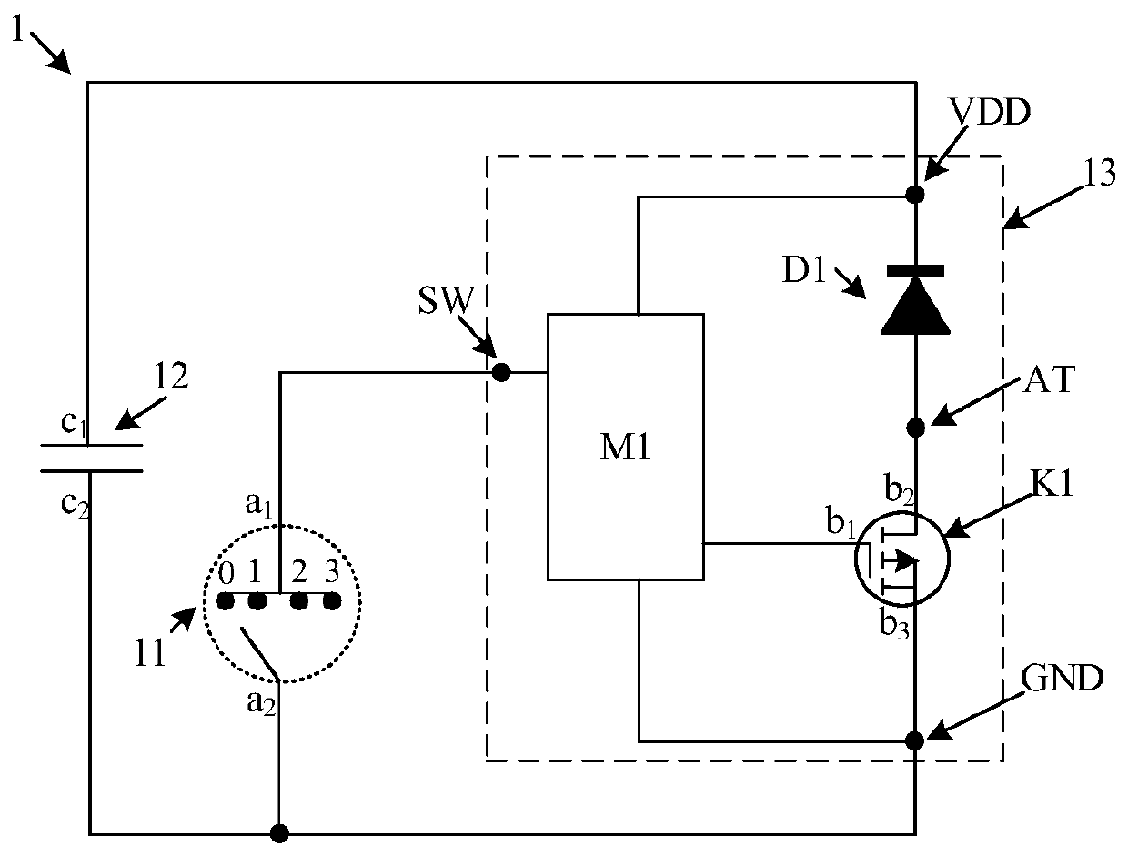
[0120] First embodiment: the switch tube K1 is a P-type MOS tube

[0121] The switch tube K1 in the control circuit 1 is a P-type MOS tube; wherein, the first end b of the switch tube (K1) 1 is the gate (marked with G), the second terminal b 2 is the source (marked with S), and the third terminal b 3 For the drain (marked with D).

[0122] Figure 9 A schematic diagram of a possible circuit connection of the electronic atomization device is shown when a P-type MOS tube is used in the control circuit provided by the present application. Such as Figure 9 As shown, the gate G of the switch K1 is connected to the logic controller M1. The source S of the switch tube K1 is connected to the anode of the power module 2 through the atomization pin AT of the control chip 13 and through the atomization module 3 . The drain D of the switch tube K1 is connected to the negative pole of the power module 2 through the ground pin GND of the control chip 13 . Also, the negative electr...

no. 2 approach

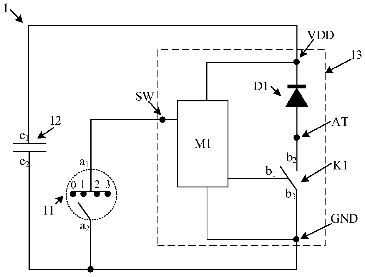
[0131] Second embodiment: the switching tube K1 is an N-type MOS tube

[0132] The switch tube K1 in the control circuit 1 is an N-type MOS tube; wherein, the first end b of the switch tube (K1) 1 is the gate G, the second terminal b 2 is the drain D, and the third terminal b 3 is the source S.

[0133] Figure 10 A schematic diagram of a possible circuit connection of the electronic atomization device is shown when an N-type MOS tube is used in the control circuit provided by this application. Such as Figure 10 As shown, the gate G of the switch K1 is connected to the logic controller M1. The drain D of the switch tube K1 is directly connected to the anode of the power module 2 via the atomization pin AT of the control chip 13 . The source S of the switch tube K1 is connected to the negative pole of the power module 2 through the ground pin GND of the control chip 13 and through the atomization module 3 . Also, the negative electrode of the power module 2 is grounde...


PUM


Abstract

The invention provides an electronic atomization device and a control circuit and method thereof, and relates to the technical field of electronic atomization. The control circuit comprises an airflowsensor, a power supply capacitor and a control chip, wherein the control chip comprises a logic controller, a one-way conduction tube, a switch tube, a power supply pin, an atomization pin and a grounding pin. The logic controller is respectively connected to the first end of the airflow sensor and the first end of the switch tube, and is connected to the first end of the power supply capacitor and the negative electrode of the one-way conduction tube through the power supply pin. And the positive electrode of the one-way conduction tube is connected to the second end of the switch tube through the atomization pin. The logic controller is connected to the third end of the switch tube, the second end of the airflow sensor and the second end of the power supply capacitor through the grounding pin. The atomization pin and the grounding pin of the control chip are used for being connected with a power module and an atomization module so as to achieve the electronic atomization function. By reducing the number of welding leads, the production cost is reduced, and the product reliability is improved.

Description

technical field [0001] The present application belongs to the technical field of electronic atomization, and in particular relates to an electronic atomization device, a control circuit and a control method thereof. Background technique [0002] As people's awareness of health and environmental protection gradually increases, more and more users begin to choose to use electronic atomization devices (such as using electronic cigarettes as a substitute for cigarettes), and the market for electronic atomization devices is also growing. In order to gain an advantage in the fierce market competition, the product quality and production cost of electronic atomization devices are issues that manufacturers need to consider. [0003] At present, in the production and manufacturing process of electronic atomization devices, chip design manufacturers usually assemble control chips, PCB boards and peripheral components into modules for sale, and actual electronic product manufacturers ne...

Claims


Application Information

Patent Timeline
IPC IPC(8): A24F40/40A24F40/46A24F40/50A24F40/51H05B45/14H05B45/325H05B47/10
CPCH05B45/14H05B45/325H05B47/10
Inventor 马美芳
Owner HANGZHOU SUNGOD SEMICON CO LTD
Why Eureka
Eureka Blog
Learn More