Technical method for staining ignition bridgehead of electronic detonator with explosive

A technology of electronic detonator and process method, which is applied in the direction of weapon accessories, fuzes, offensive equipment, etc., can solve the problems of poor firing reliability, accidents, and increased cost of electronic detonator delay modules, etc., to achieve cost reduction and reliable quality.

Inactive Publication Date: 2018-08-21
北京煋邦数码科技有限公司
View PDF5 Cites 2 Cited by
  • Summary
  • Abstract
  • Description
  • Claims
  • Application Information

AI Technical Summary

Problems solved by technology

[0003] The ignition bridge head produced by the existing ignition bridge tip dipping method is either too insensitive, which leads to an increase in the cost of the electronic detonator delay module, and poor ignition reliability; or is too sensitive to cause production, transportation and use safety problems, and even cause accidents

Method used


Image

  • Technical method for staining ignition bridgehead of electronic detonator with explosive

Examples


specific Embodiment 1

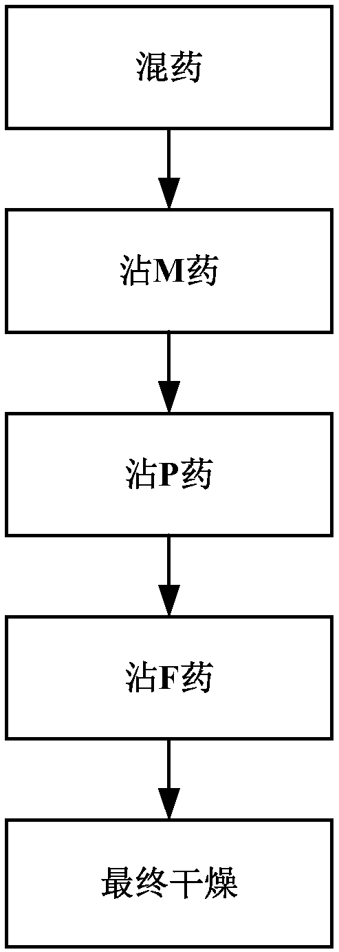
[0029] Specific embodiment 1: (1) mixed medicine: make medicine head raw material, described medicine head raw material comprises M medicine, P medicine and F medicine, and described P medicine is the gas production class medicine, comprises potassium picrate and red lead; The F medicine is a moisture-proof medicine; the M medicine is a medicine with a higher sensitivity than the P medicine and the F medicine, and the main component is DDNP;

[0030] (2) Dip M drug: Manually insert the bridge wire of the bridge head into the M drug whose main component is DDNP after dipping it once, turn it 180°, and then dip it again with DDNP M drug, and then put it into the infrared drying equipment for drying, after drying, cycle the above steps again, and alternately carry out twice, that is, complete the process of dipping M drug;

[0031] (3) Dip P medicine: Manually insert the bridge wire of the burning bridge head that has been dried in step (2) into the P medicine made of mixed medic...

specific Embodiment 2

[0034] Specific embodiment 2: (1) mixed medicine: make medicine head raw material, described medicine head raw material comprises M medicine, P medicine and F medicine, and described P medicine is the gas production class medicine, comprises potassium picrate and red lead; The F medicine is a moisture-proof medicine; the M medicine is a medicine with a higher sensitivity than the P medicine and the F medicine, and the main component is DDNP;

[0035] (2) Dip M medicine: first clamp the connecting plate part of the fire bridge head in the fire bridge head medicine dipping plate, then fix the fire bridge head medicine dipping plate on the medicine dipping device, and the bridge wire of the fire bridge head on the medicine dipping device faces Next, dip into the M drug whose main component is DDNP after dipping once, automatically turn the drug dipping device 180°, then dip the M drug whose main component is DDNP again, and then pass it through the tunnel furnace The crawler is c...


PUM


Abstract

The invention relates to a technical method for staining an ignition bridgehead of an electronic with an explosive. The method comprises the following steps: (1) explosive mixing: preparing an explosive head raw material which comprises an M explosive, a P explosive and an F explosive; (2) M explosive staining: extending a bridge wire of the ignition bridgehead into the M explosive obtained by explosive mixing to stain with the explosive and drying the bridge wire once each time, and staining with the M explosive and drying the bridge wire alternately twice; (3) P explosive staining: extendingthe bridge wire, dried in step (2), of the ignition bridgehead into the P explosive to stain with the explosive, drying the bridge wire, and staining with the P explosive and drying the bridge wire alternately for three to four times; (4) F explosive staining: extending the bridge wire dried in step (3), of the ignition bridgehead into the F explosive to stain with the F explosive, drying the bridge wire, and staining with the F explosive and drying the bridge wire alternately; (5) final drying: performing final drying on the ignition bridgehead dried in step (4). The ignition bridgehead sensitivity produced according to the method provided by the invention is moderate in sensitivity, and reliable in quality, safety in production, transportation and use is ensured, and the cost of an electronic detonator delay module is greatly reduced.

Description

technical field [0001] The invention relates to the technical field of production of firing bridge heads of electronic detonators, in particular to a process method for dipping the firing bridge heads of electronic detonators with medicine. Background technique [0002] In recent years, due to the wide application of blasting technology, electronic detonators are widely used in the blasting process. The ignition part is also called the ignition bridge head, including the bridge wire and ignition powder. Drop-shaped ignition element. [0003] The ignition bridgehead produced by the existing ignition bridgehead dipping method is either too insensitive to increase the cost of the electronic detonator delay module and has poor ignition reliability; or it is too sensitive to cause production, transportation and use safety problems, and even cause accidents. Contents of the invention [0004] In view of this, the purpose of the present invention is to provide an electronic deto...

Claims


Application Information

Patent Timeline
Patent Type & Authority Applications(China)
IPC IPC(8): F42C19/12
CPCF42C19/12
Inventor 张英豪张立明姚升武肖武红
Owner 北京煋邦数码科技有限公司
Why Eureka
Try Eureka