A common voltage drive circuit, its control method, and a display device

A common voltage, driving circuit technology, applied in static indicators, instruments, etc., can solve the problem of residual image, achieve the effect of solving the residual charge or residual image, and improve the visual viewing effect

Active Publication Date: 2021-02-19
KUSN INFOVISION OPTOELECTRONICS
View PDF6 Cites 0 Cited by
  • Summary
  • Abstract
  • Description
  • Claims
  • Application Information

AI Technical Summary

Problems solved by technology

[0005] The main purpose of the present invention is to propose a common voltage drive circuit, its control method, and a display device, aiming to solve the problem of image sticking in the prior art when the liquid crystal display device switches from a narrow viewing angle to a wide viewing angle

Method used


Image

  • A common voltage drive circuit, its control method, and a display device
  • A common voltage drive circuit, its control method, and a display device
  • A common voltage drive circuit, its control method, and a display device

Examples


no. 1 example

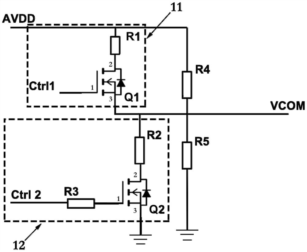
[0038] Such as figure 1 As shown, the first embodiment of the present invention provides a common voltage drive circuit, the common voltage drive circuit includes a first power switch Q1 and a second power switch Q2 connected in parallel;

[0039] The first end of the first power switch tube Q1 (indicated by 1 in the figure, similar to the following) is connected to the first control signal Ctrl1, and the second end of the first power switch tube Q1 is connected to the signal input terminal AVDD, The third terminal of the first power switch tube Q1 is connected to the signal output terminal Vcom;

[0040] The first terminal of the second power switch tube Q2 is connected to the second control signal Ctrl2, the second terminal of the second power switch tube Q2 is connected to the signal output terminal Vcom, and the third terminal of the second power switch tube Q2 connected to the ground terminal.

[0041] In this embodiment, both the first power switch tube and the second ...

no. 2 example

[0061] The second embodiment of the present invention provides a display device, and the display device includes the common voltage driving circuit described in the first embodiment.

[0062] In the display device provided by the embodiment of the present invention, by controlling the power switch tube of the common voltage drive circuit, the output common voltage has a certain bias voltage, which solves the problem of charge residue or residual charge that exists when the liquid crystal display device switches from a narrow viewing angle to a wide viewing angle. It solves the problem of shadows and improves the user's visual viewing effect.

no. 3 example

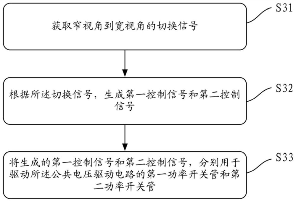
[0064] refer to image 3 , image 3 For the control method of the common voltage drive circuit provided by the third embodiment of the present invention, the content of the common voltage drive circuit may refer to the content described in the first embodiment. The method comprises the steps of:

[0065] S31. Obtain a switching signal from a narrow viewing angle to a wide viewing angle;

[0066] In this embodiment, a switching signal from a narrow viewing angle to a wide viewing angle may be obtained by detecting a rising edge signal or a falling edge signal of a Hybrid Viewing Angle (HVA).

[0067] S32. Generate a first control signal and a second control signal according to the switching signal;

[0068] S33. Use the generated first control signal and second control signal to drive the first power switch tube and the second power switch tube of the common voltage drive circuit respectively.

[0069] In order to better illustrate this embodiment, the following combination...


PUM


Abstract

The invention discloses a common voltage driving circuit and a control method and display device thereof. The common voltage driving circuit comprises a first power switching tube and a second power switching tube which are in parallel connection; a first end of the first power switching tube is connected with a first control signal, a second end of the first power switching tube is connected witha signal input end, and a third end of the first power switching tube is connected with a signal output end; a first end of the second power switching tube is connected with a second control signal,a second end of the second power switching tube is connected with the signal output end, and a third end of the second power switching tube is connected with a grounding end. According to the common voltage driving circuit and the control method and display device thereof, by controlling the power switching tube of the common voltage driving circuit, a certain amount of offset voltage exists in output common voltage, the problem of charge residue or charge ghosting when a narrow viewing angle is switched to a wide viewing angle in a liquid crystal displaying device is solved, and the visual viewing effect of a user is improved.

Description

technical field [0001] The invention relates to the field of display technology, in particular to a common voltage drive circuit, a control method thereof, and a display device. Background technique [0002] Due to the advantages of thinness, energy saving, and no radiation, liquid crystal display devices are widely used in electronic equipment such as televisions, personal computers, tablet computers, PDAs (Personal Digital Assistants), mobile phones, and digital cameras. [0003] Liquid crystal display devices have different working modes, such as wide and narrow viewing angle modes. When the liquid crystal display device is switched from a narrow viewing angle to a wide viewing angle, the charge in the display panel needs to be switched, and the user may find charge residue in a brighter picture (such as a white screen), or find afterimages in a wide viewing angle (that is, a residual image). ), which makes the user's visual viewing effect poor. [0004] In view of the ...

Claims


Application Information

Patent Timeline
Patent Type & Authority Patents(China)
IPC IPC(8): G09G3/36
CPCG09G3/36G09G3/3696
Inventor 林沛炀蔡浩荀文东
Owner KUSN INFOVISION OPTOELECTRONICS
Why Eureka
Try Eureka