Power distribution box

A distribution box and box technology, applied in the substation/distribution device shell, electrical components, substation/switch layout details, etc., can solve the short circuit of the electrical components of the distribution box, affecting the normal use of the distribution box, and affecting the electrical equipment Use and other problems to achieve the effect of improving heat dissipation, ensuring drying, and prolonging service life

Inactive Publication Date: 2018-08-21
FOSHAN ENCI TECH CO LTD
View PDF0 Cites 2 Cited by
  • Summary
  • Abstract
  • Description
  • Claims
  • Application Information

AI Technical Summary

Problems solved by technology

[0002] The power distribution cabinet is an outdoor cabinet used to place electrical equipment, but in the current power distribution cabinet, in wet or rainy weather, rainwater can easily enter the power distribution cabinet along the cabinet, which not only affects the use of electrical equipment, Moreover, it is easy to cause failures in use, resulting in short circuit and damage to the electrical components in the distribution box, which affects the normal use of the distribution box. In addition, the temperature of the distribution box will gradually increase with the use of the distribution box, which will easily damage the equipment in the box.

Method used


Image

  • Power distribution box
  • Power distribution box
  • Power distribution box

Examples


Embodiment Construction

[0021] The technical solutions of the present invention will be clearly and completely described below through specific embodiments.

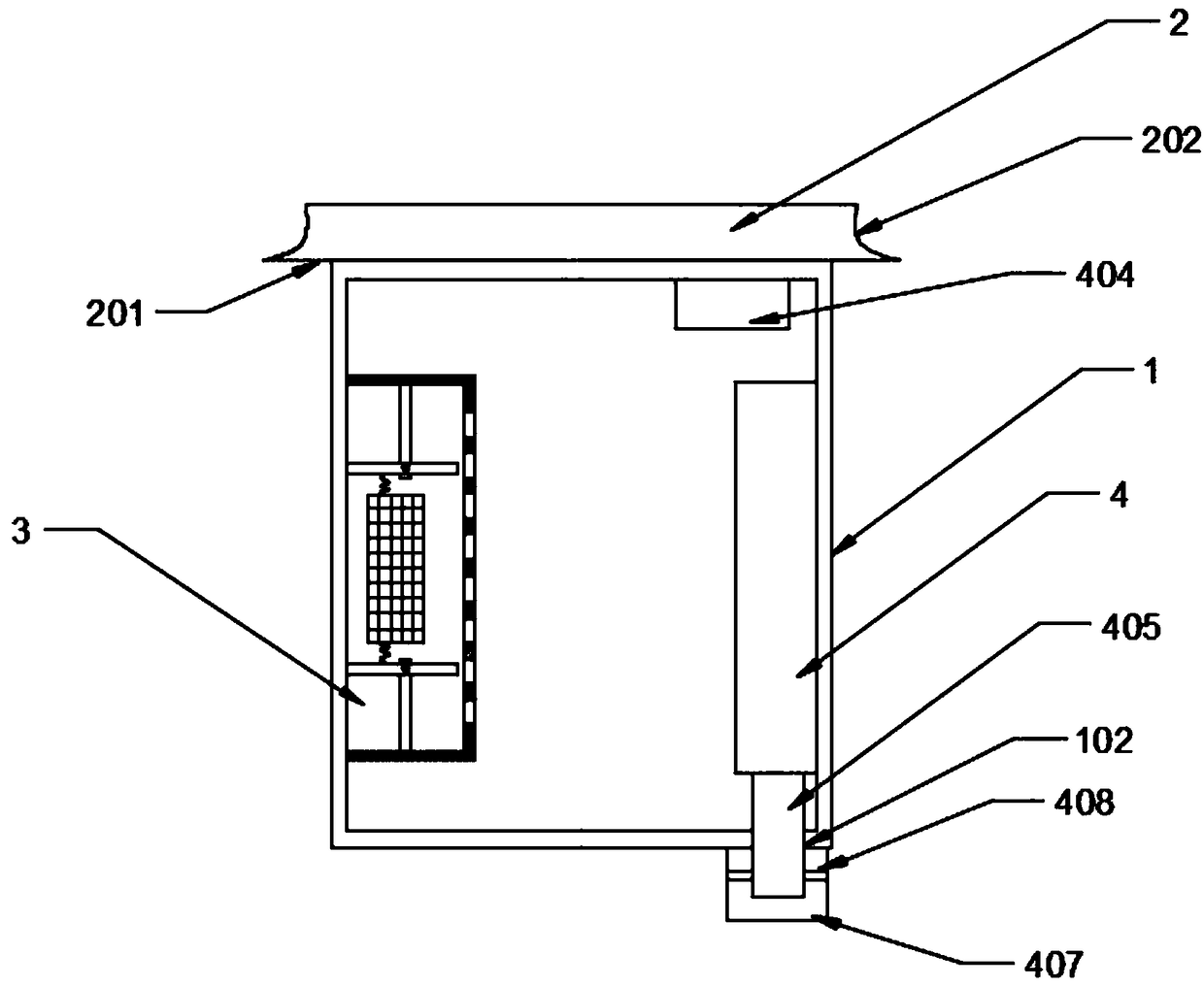
[0022] Such as figure 1 As shown, a distribution box includes a box body 1 , a shielding cover 2 , a moisture-proof device 3 and a heat dissipation device 4 .

[0023] The top of the box body 1 is provided with a shielding cover 2, the lower end surface of the shielding cover 2 is fixedly connected with the top outer wall of the box body 1, and the area of ​​the lower end surface 201 of the shielding cover 2 is greater than the area of ​​the top surface of the box body 1. The outer peripheral surface 202 of the shielding cover 2 is a concave curved surface. When rainwater falls, the rainwater will slide out along the outer peripheral wall of the shielding cover 2 in a parabola, and will not slide down along the outer peripheral wall of the box body 1 .

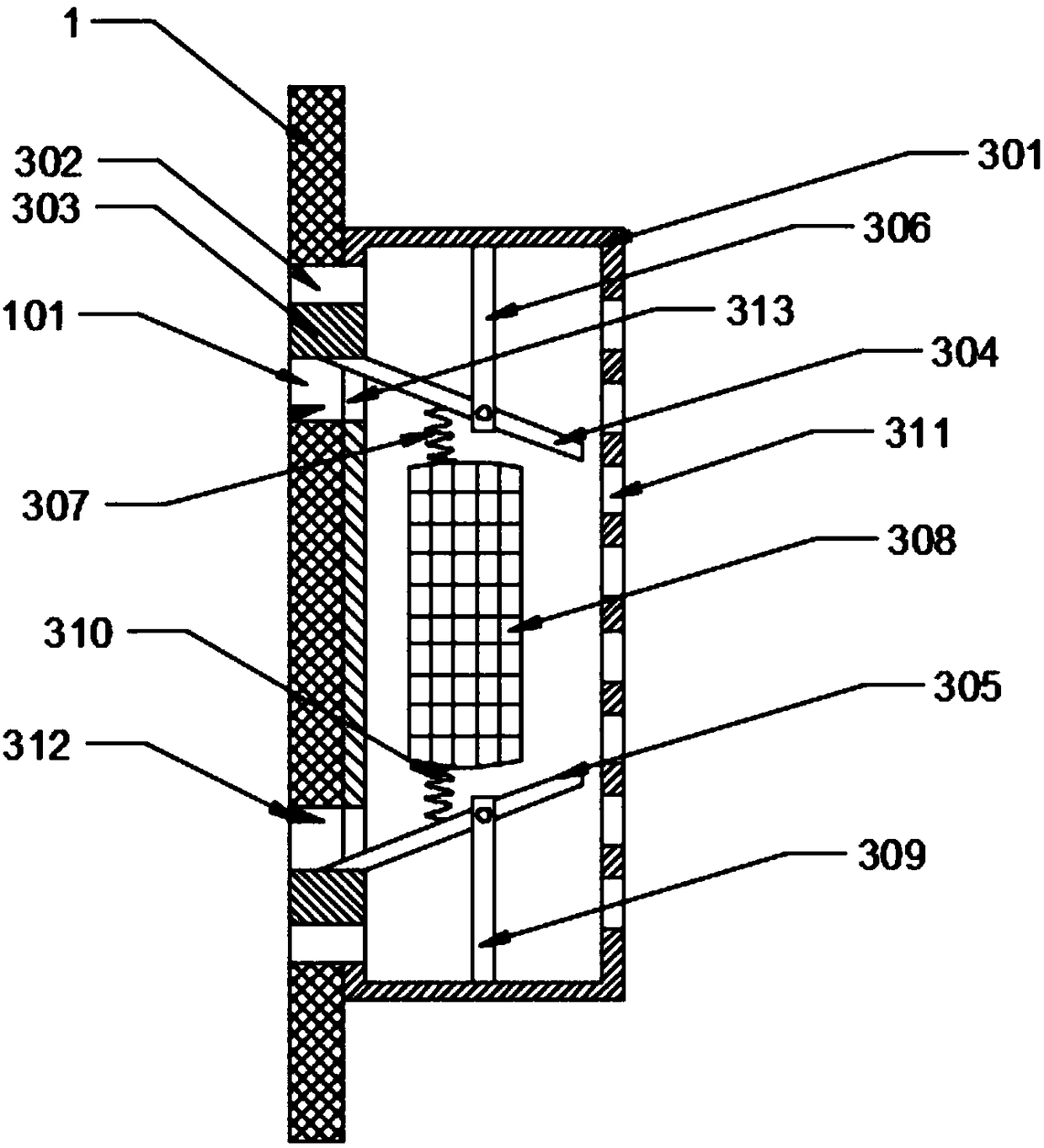
[0024] Such as figure 2 As shown, a moisture-proof device 3 is provided in the box body ...


PUM


Abstract

The invention discloses a power distribution box. A shielding cover is arranged on the top of a box body; the peripheral surface of the shielding cover is a concave curved face; the inner side wall ofthe box body is provided with a moisture-proof device and a heat dissipation device; a shell is fixed on the inner wall of the box body; a moisture channel opening is formed between the shell and thebox body; the moisture channel opening is internally provided with a valve seat; the valve seat is internally telescopically provided with a valve plate; the valve plate is arranged at the position of the moisture channel opening in a sliding manner; the valve plate is used for closing or opening the moisture channel opening in a telescopic state; a movable rod is in contact with the valve plateto control the valve plate to perform a telescopic motion so as to open and close the moisture channel opening; the movable rod is rotatably connected around a fixed rod; the fixed rod is fixed on theinner wall of the box body; a moisture absorbent is arranged inside a mesh bag; the mesh bag is externally expanded or internally shrunk through the volume change of the moisture absorbent; the meshbag enables the movable rod to rotate; the movable rod controls the valve plate to close or open the moisture channel opening; and a plurality of moisture inlets are formed in the other side of the shell. According to the power distribution box, the service lives of components and parts inside the power distribution box are prolonged.

Description

technical field [0001] The invention relates to the field of power distribution equipment, in particular to a power distribution box. Background technique [0002] The power distribution cabinet is an outdoor cabinet used to place electrical equipment, but the current power distribution cabinet, in wet or rainy weather, rainwater can easily enter the power distribution cabinet along the cabinet, which not only affects the use of electrical equipment, And it is easy to cause use failure, cause short circuit and damage of electrical components in the distribution box, and affect the normal use of the distribution box. In addition, the operating temperature of the distribution box will gradually increase, which will easily damage the equipment in the box. Contents of the invention [0003] In order to solve the above technical problems, the present invention provides a distribution box. [0004] Technical scheme of the present invention is realized like this: [0005] A dis...

Claims


Application Information

Patent Timeline
IPC IPC(8): H02B1/46H02B1/56H02B1/28
CPCH02B1/46H02B1/28H02B1/565
Inventor 李修龙
Owner FOSHAN ENCI TECH CO LTD
Why Eureka
Try Eureka