

Physical experimental platform
A technology for physical experiments and platforms, applied in the field of experimental platforms, can solve the problems of large space occupation, excessive time consumption, waste of resources, etc., and achieve the effect of improving efficiency and speed, saving space and time, and improving efficiency.
- Summary
- Abstract
- Description
- Claims
- Application Information
AI Technical Summary
Problems solved by technology
Method used
Image

Examples
Embodiment Construction
[0044] The present invention is described in further detail now in conjunction with accompanying drawing. These drawings are all simplified schematic diagrams, which only illustrate the basic structure of the present invention in a schematic manner, so they only show the configurations related to the present invention.
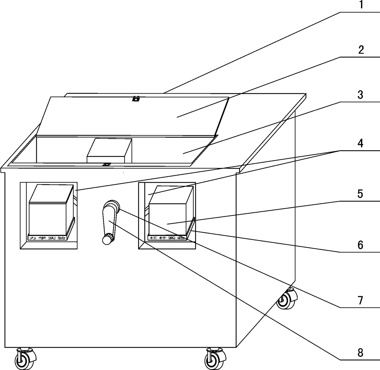
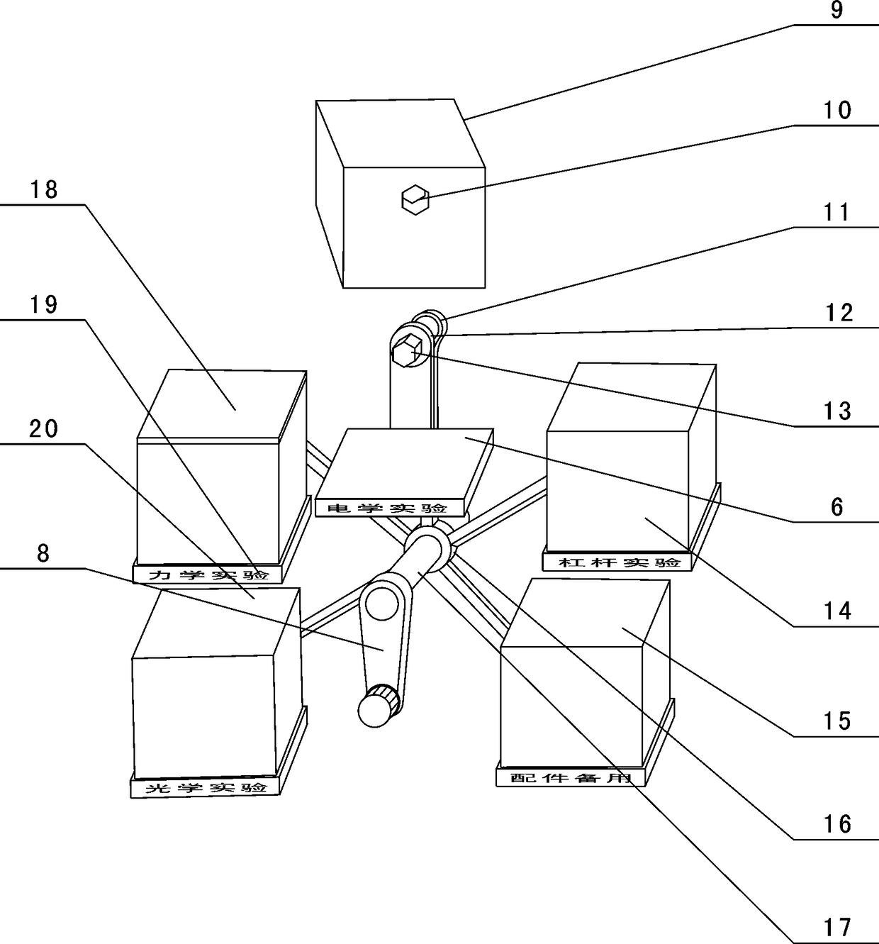
[0045] combined with figure 1 --The structure provided in 9, a kind of physical experiment platform, comprises table body 1, is provided with concave cavity 78 at the bottom of the front panel of described table body 1, is provided with two in described concave cavity 78 The uprights 79 parallel to each other are respectively sleeved with a swivel 80 on each upright 79, and a seat 81 is horizontally connected to one side of each swivel 80, and a rotating seat 81 is provided. , convenient for storage and does not affect the overall appearance of the table body 1, an expansion box 85 is provided on the upper part of the front panel of the table body 1, and seve...
PUM
 Abstract
Description
Claims
Application Information