
High-speed stirring and periodic discharging device for mortar

A high-speed mixing and discharging device technology, applied in cement mixing devices, unloading devices, clay preparation devices, etc., can solve problems such as difficulty in meeting construction requirements, dead ends of mixing, and low mortar output, and achieve compact and perfect structure design. Fast speed and good mortar quality

Active Publication Date: 2018-08-24
浙江恒尊新材料科技有限公司
View PDF6 Cites 8 Cited by
  • Summary
  • Abstract
  • Description
  • Claims
  • Application Information

AI Technical Summary

Problems solved by technology

[0002] Mortar is often used in construction work, and mortar mixing has its special operation requirements. In actual use, the pre-preparation time is long, and mortar cannot be produced quickly or even immediately, resulting in construction in a specific environment. A lot of inconvenience, especially the mortar mixing operation in a narrow space, the mortar output is low, and it is difficult to meet the construction requirements, which requires a mortar mixing device that can quickly mix and discharge the material to solve this problem
[0003] In order to solve the above problems, the present invention is proposed, which overcomes the currently used mortar mixing device. Due to the use of a fixed-length mixing structure, in the actual mixing operation, due to the existence of gaps in the mixing, there are dead spots in the mixing, resulting in uneven mixing, incomplete mixing, etc. The problem is to solve the problems of the currently used mortar mixing device. Due to the imperfect or even missing structure of the auxiliary discharge, during the rapid discharge process, there will be a period of time for discharging mortar stirring, and the quality of the mortar is poor, which makes the present invention have a compact structure design. Perfect, fast and thorough mixing, good mortar quality, stable transmission, high output quality, etc.

Method used


Image

  • High-speed stirring and periodic discharging device for mortar
  • High-speed stirring and periodic discharging device for mortar
  • High-speed stirring and periodic discharging device for mortar

Examples


Embodiment Construction

[0020] The following will clearly and completely describe the technical solutions in the embodiments of the present invention with reference to the accompanying drawings in the embodiments of the present invention. Obviously, the described embodiments are only some, not all, embodiments of the present invention. Based on the embodiments of the present invention, all other embodiments obtained by persons of ordinary skill in the art without making creative efforts belong to the protection scope of the present invention.

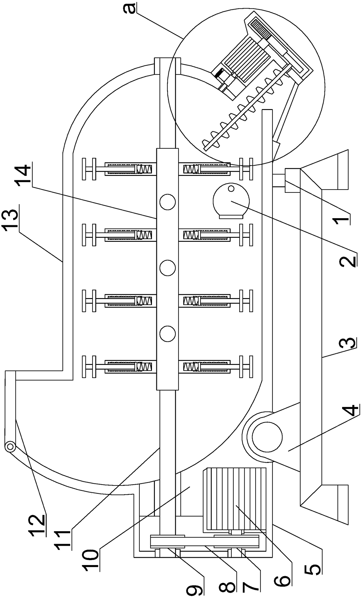
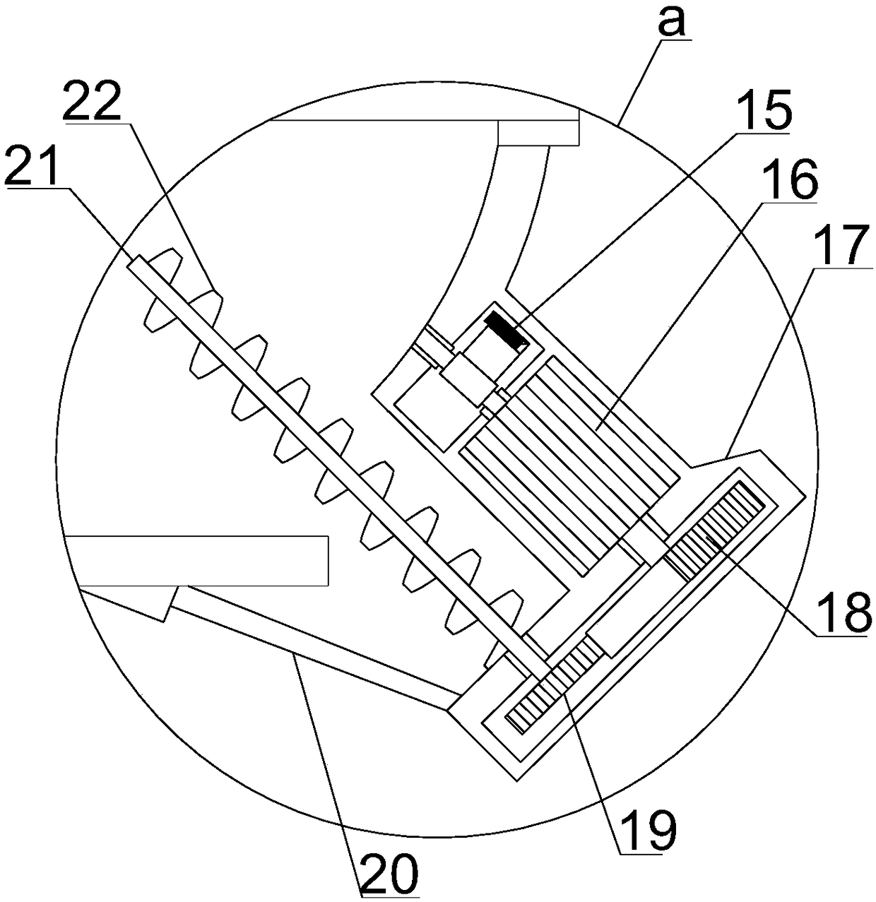
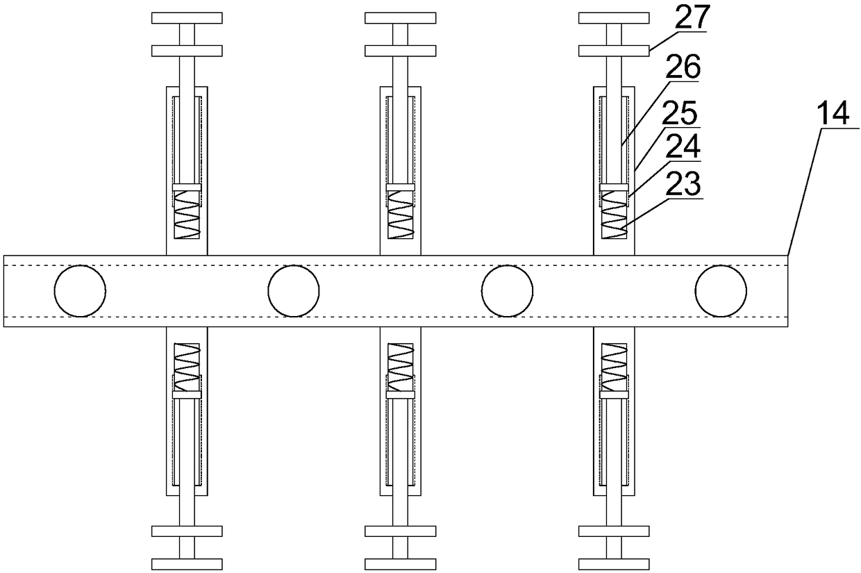
[0021] see Figure 1~6 , in an embodiment of the present invention, a mortar high-speed stirring periodical discharge device includes a high-speed stirring support module and a periodic rotating discharge module, the high-speed stirring support module includes a support mounting plate 3, and the lower end of the support mounting plate 3 is left and right Both ends are symmetrically provided with support installation columns, and the lower ends of the support i...


PUM


Abstract

The invention discloses a high-speed stirring and periodic discharging device for mortar. The high-speed stirring and periodic discharging device for the mortar comprises a high-speed stirring supporting module and a periodic rotary discharging module, wherein the high-speed stirring supporting module comprises a supporting mounting plate, the left upper end of the supporting mounting plate is provided with a feeding transmission plate through triangular supporting plates which are arranged in a front-back symmetry mode and a supporting rotating shaft which penetrates through the upper ends ofthe triangular supporting plates, a stirring discharging cylinder is horizontally arranged on the right side of the feeding transmission plate, a stirring transmission cover is arranged at the left end of the feeding transmission plate, and a driving stirring motor is inlaid in the left lower corner of the feeding transmission plate in a horizontal and leftward mode; and the left end of the driving stirring motor is matched with the stirring transmission cover and is coaxially provided with a driving belt wheel through a horizontally-arranged motor rotating shaft, and the upper half section of the stirring transmission cover horizontally penetrates through the feeding transmission plate and is horizontally provided with a stirring operation shaft. The high-speed stirring and periodic discharging device for the mortar has the advantages that the structure design is compact and complete, the stirring speed is high, stirring is thorough, the mortar quality is good, transmission is stable, and the discharging quality is high.

Description

technical field [0001] The invention relates to a construction machine, in particular to a high-speed stirring cycle discharge device for mortar. Background technique [0002] Mortar is often used in construction work, and mortar mixing has its special operation requirements. In actual use, the preparation time is long, and mortar cannot be produced quickly or even immediately, resulting in construction and use in specific environments. It is very inconvenient, especially the mortar mixing operation in a small space, the mortar output is low, and it is difficult to meet the construction requirements, which requires a mortar mixing device that can quickly mix and discharge the material to solve this problem. [0003] In order to solve the above problems, the present invention is proposed, which overcomes the currently used mortar mixing device. Due to the use of a fixed-length mixing structure, in the actual mixing operation, due to the existence of a gap in the mixing, there...

Claims


Application Information

Patent Timeline
Patent Type & Authority Applications(China)
IPC IPC(8): B28C5/14B28C5/08B28C7/16
CPCB28C5/0806B28C5/0856B28C5/148B28C7/162B28C7/167
Inventor 林少忠
Owner 浙江恒尊新材料科技有限公司
Learn More