Driving force distribution apparatus

一种分配装置、驱动力的技术,应用在传动装置、差速传动装置、齿轮传动装置等方向,能够解决装置大型化、重量增大、难以充分确保环齿轮支承刚性等问题,达到抑制大型化的效果

Active Publication Date: 2018-08-24
JTEKT CORP
View PDF7 Cites 2 Cited by
  • Summary
  • Abstract
  • Description
  • Claims
  • Application Information

AI Technical Summary

Problems solved by technology

In this structure, the ring gear has a cantilever structure, so it is difficult to ensure sufficient support rigidity of the ring gear, and the driving force transmitted to the ring gear may reduce the meshing accuracy with the drive pinion, resulting in vibration and noise.
In addition, if the bearing is enlarged to ensure the support rigidity of the ring gear, the device will be enlarged and the weight will be increased.

Method used


Image

  • Driving force distribution apparatus
  • Driving force distribution apparatus
  • Driving force distribution apparatus

Examples


no. 1 approach

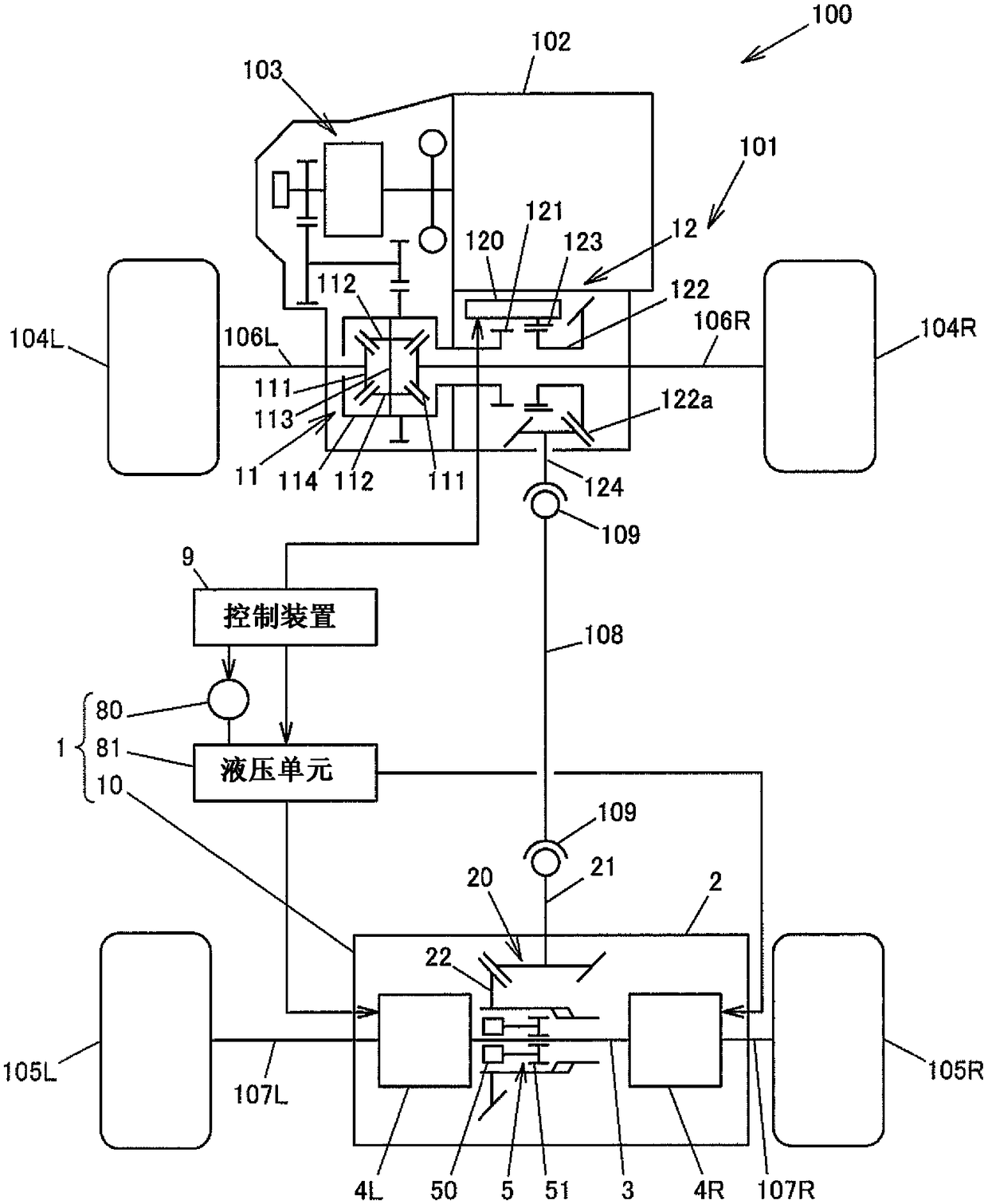
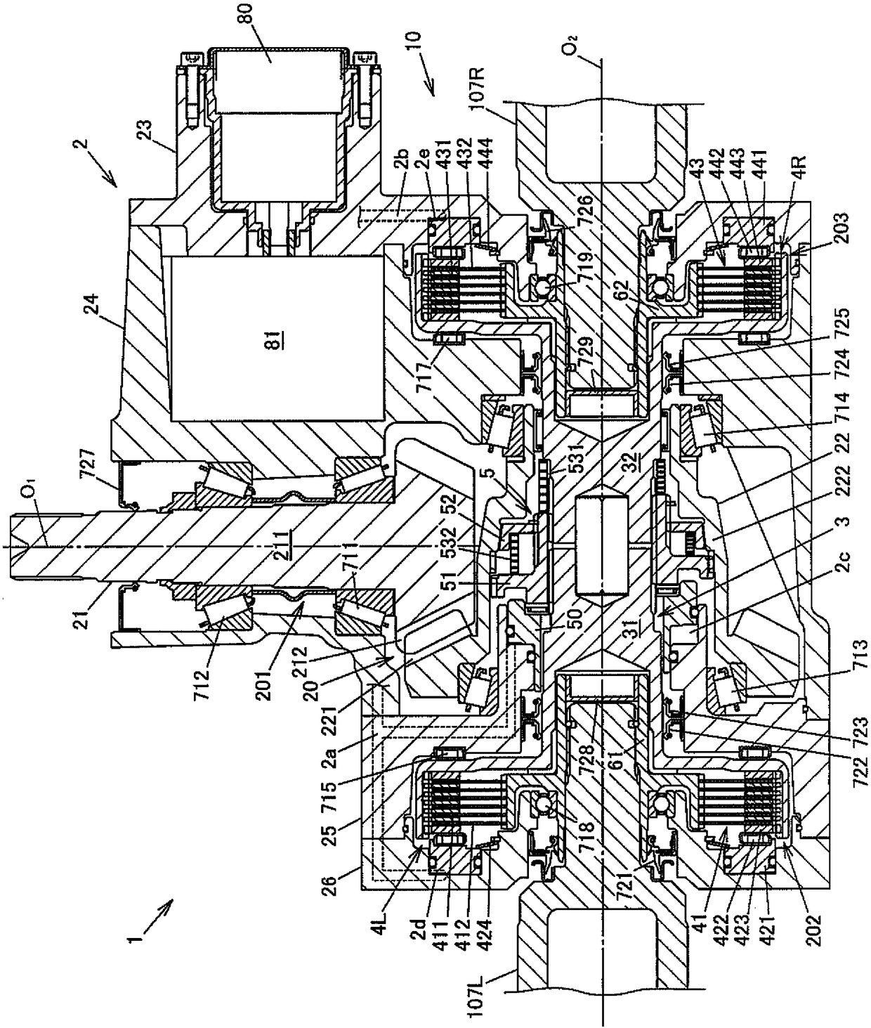
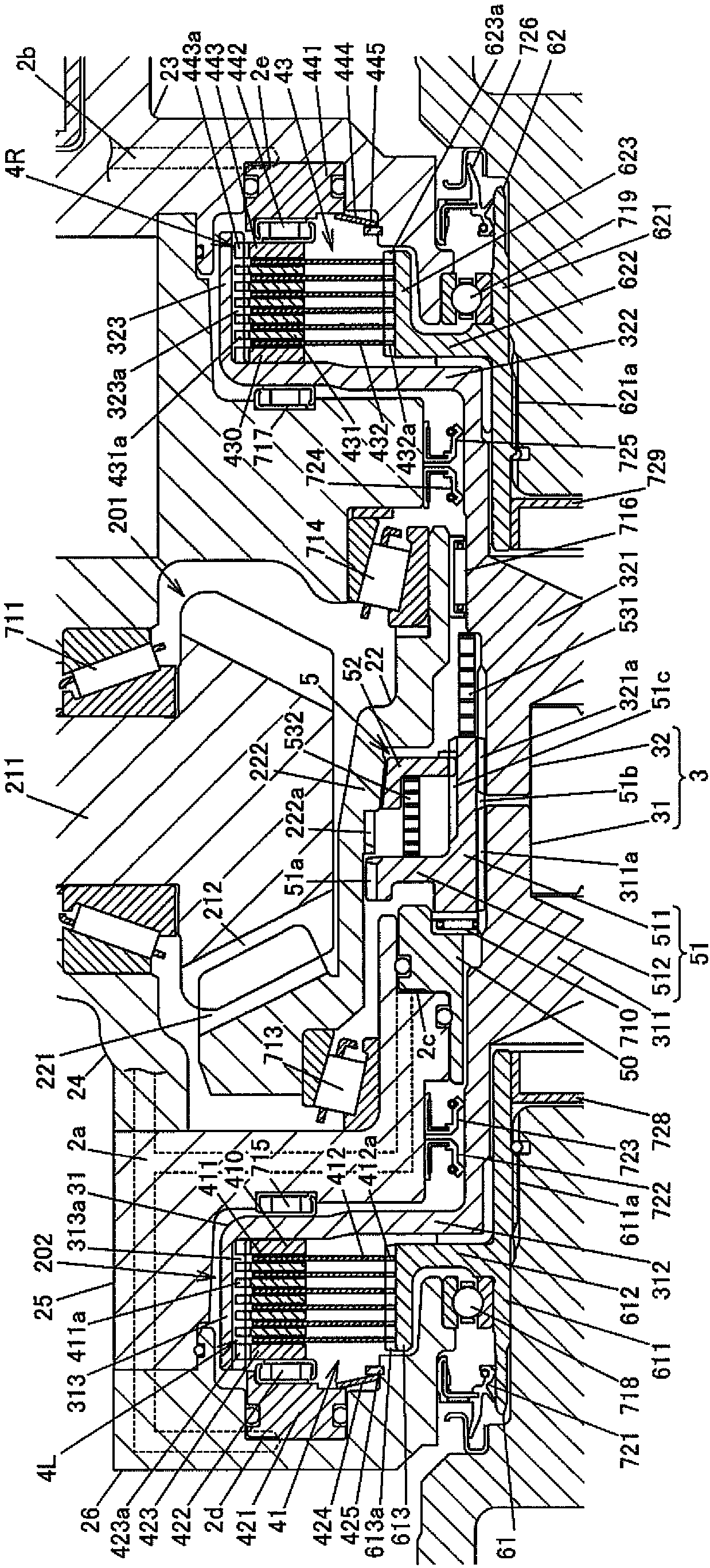
[0021] figure 1 It is a configuration diagram schematically showing a configuration example of a four-wheel drive vehicle equipped with the driving force distribution device according to the first embodiment of the present invention.

[0022] The four-wheel drive vehicle 100 includes an engine 102 as a driving source for generating driving force for traveling, a transmission 103, a pair of left and right front wheels 104L and 104R as main drive wheels, and a pair of left and right rear wheels 105L as auxiliary drive wheels. , 105R, the driving force transmission system 101 capable of transmitting the driving force of the engine 102 to the front wheels 104L, 104R and the rear wheels 105L, 105R, and the control device 9 .

[0023] This four-wheel drive vehicle 100 can be used in a four-wheel drive state in which the driving force of the engine 102 is transmitted to the front wheels 104L, 104R and rear wheels 105L, 105R, and a two-wheel drive state in which the driving force of t...


PUM


Abstract

The present invention provides a driving force distribution apparatus (1). The driving force distribution apparatus includes an orthogonal gear pair (20) constituted by a pinion gear shaft (21) and aring gear member (22), a casing (2) that houses the orthogonal gear pair (20), an intermediate rotational member (3) coaxially rotatable relative to the ring gear member (22), a clutch member (51) configured to couple the ring gear member (22) and the intermediate rotational member (3) to each other, and first and second driving force adjustment mechanisms (4L, 4R) configured to adjust a driving force to be transmitted from the intermediate rotational member (3) to first and second output rotational members (61, 62). The ring gear member (22) has a ring gear portion (221) and a tubular portion(222). At two positions between which the ring gear portion (221) is interposed in an axial direction, the tubular portion (222) is rotatably supported by a pair of bearings (713, 714).

Description

technical field [0001] The present invention relates to a driving force distribution device for a vehicle that outputs input driving force from first and second output rotating members. Background technique [0002] Conventionally, a driving force distribution device that outputs input driving force from first and second output rotating members is mounted on, for example, a four-wheel drive vehicle. Such a driving force distribution device is capable of adjusting a distribution ratio of the driving force output from the first output rotating member to the driving force output from the second output rotating member according to the running state of the vehicle. For example, refer to JP-A-2015-120501. [0003] The driving force distribution device (left and right driving force distribution unit) described in Japanese Patent Application Laid-Open No. 2015-120501 includes: a pair of orthogonal gears, the driving pinion gear and the driving pinion gear to make the gear shaft ort...

Claims


Application Information

Patent Timeline
Patent Type & Authority Applications(China)
IPC IPC(8): B60K17/34B60K17/08
CPCB60K17/08B60K17/34B60K17/02F16H48/19F16D25/10B60K2023/0841B60K17/344B60K23/0808B60K2023/085F16D25/082F16H1/14F16D25/0638
Inventor 藤井则行
Owner JTEKT CORP
Why Eureka
Try Eureka