Anti-sway device for pull-down crane

A crane and pull-down technology, which is applied in the field of pull-down crane anti-sway devices, can solve the problems of excessive support arm weight and lever arm, single-dimensional anti-sway, and large crane gravity, so as to reduce the difficulty of lifting and reduce the lifting space. Wide and anti-shake effect

Active Publication Date: 2020-01-07
YANSHAN UNIV
View PDF10 Cites 0 Cited by
  • Summary
  • Abstract
  • Description
  • Claims
  • Application Information

AI Technical Summary

Problems solved by technology

The existing technology is still unable to propose a better electric solution for the anti-sway modification of the ship crane
Patent US6439407B1 proposes to use a single slider for lifting, and add two anti-sway ropes on the side of the slider, and then connect the weight to the bottom of the slider through a six-degree-of-freedom parallel rope mechanism. The disadvantage is that the part that needs to be controlled Too many, and the six-degree-of-freedom parallel rope pull mechanism itself requires a certain amount of space
Patent EP2526042B1 proposes a crane that can prevent shaking along the direction of the boom and its vertical direction. Its disadvantage is that the lifting part cannot adapt to the narrow cargo storage environment; patent CN201621218272. The disadvantage is that the weight and force arm of the support arm at the end of the multi-stage movable arm are too large, occupying space, and can only prevent shaking in a single dimension
Patent CN105621275A proposes a crane using a parallel mechanism to prevent shaking. It adds a three-branch parallel mechanism under the crane. The disadvantage is that the gravity of the crane is too large, and the output requirements for the parallel mechanism are relatively high.
Patent US7367464B1, this patent proposes a crane that uses two rotating beams to control and restrain heavy objects from shaking in the direction of the boom. The disadvantage is that it can only prevent shaking in one dimension

Method used


Image

  • Anti-sway device for pull-down crane
  • Anti-sway device for pull-down crane
  • Anti-sway device for pull-down crane

Examples


Embodiment 1

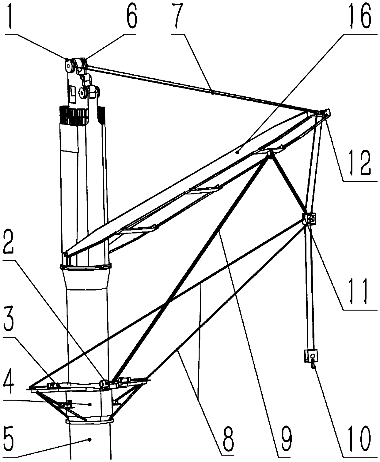
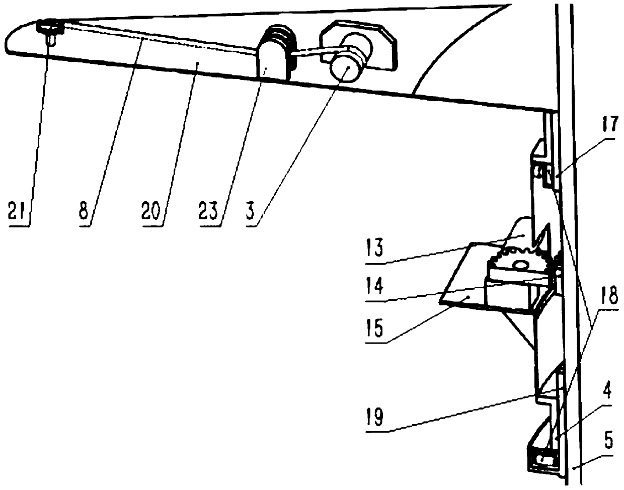
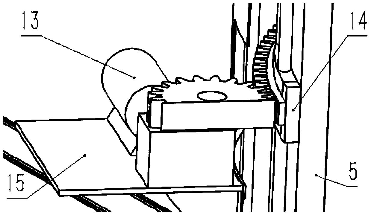
[0031] exist figure 1 and figure 2 In the schematic diagram of the anti-sway device of the pull-down crane shown, the rotating drum device is arranged on the base column 5 of the gram crane, and the base column in the rotating drum 4 is sequentially provided with a set of fixed poles along the circumference of the base column from top to bottom. Connected upper swivel guide rail 17, rotating gear 14 and lower swivel guide rail 19, the upper and lower ends of the drum are provided with upper and lower sets of casters 18 that are respectively pressed against the upper and lower swivel guide rails, and the drum driving device 13 includes a drive Motor and driving gear, wherein the driving motor is fixed on the rotating drum driving device fixing plate 15 on the rotating drum drum wall, the rotating drum drum wall above the rotating drum driving device fixing plate is provided with an opening, and the driving gear is located on the driving motor on the output shaft and meshes wi...

Embodiment 2

[0043] Symmetrically arranged inner and outer two sets of cable mechanisms with the same structure, such as Figure 10 As shown, the cable actuator 24 is located in the middle of the wing-shaped support frame, that is, between the cable drive device 3 and the cable fixed pulley 21, and the lower end of the cylinder barrel of the cable actuator is fixedly connected to the wing-shaped support frame. The upper end of the cylinder is connected with the lower end of the guy wire actuator, and a guy wire actuator pressing pulley is arranged at the upper end of the guy wire actuator, and two guy wire pressure rollers 23 are fixed on both sides of the guy wire actuator cylinder. One end of the dragline 8 is drawn out from the dragline driving device, and the other end respectively goes around the dragline pinch roller, the dragline actuator pinch pulley, another dragline pinch wheel and the dragline fixed pulley, and finally fixes it on the pulley. on a rectangular frame. Other compo...


PUM


Abstract

The invention discloses a pull-down type crane shaking preventive device which comprises a pulling rope mechanism, a loading rope mechanism, towing rope mechanisms, a rotary drum device, a pulling block and loading pulleys. The rotary drum device is arranged on a crane foundation pillar, the loading rope mechanism comprises a loading rope tail end fixed pulley, a loading rope driving device and aloading rope, the towing rope mechanisms comprise towing rope driving devices, wing-shaped support frames, rotary drum driving devices, towing ropes and towing rope fixed pulleys, the locations of heavy objects in spaces are jointly controlled by the pulling rope mechanism, the loading rope mechanism and the towing rope mechanisms, and shaking of the heavy objects can be synchronously restrained by a single towing rope actuator and two towing rope actuators on the wing-shaped support frames. The pull-down type crane shaking preventive device has the advantages that the pull-down type crane shaking preventive device is high in load and wide in hoisting space domain, effects of quickly reducing shaking of the hoisted heavy objects along the directions perpendicular to a suspension arm and along the direction of the suspension arm to a great extent can be realized by the pull-down type crane shaking preventive device, and requirements of narrow and long goods placing environments can be met.

Description

technical field [0001] The invention relates to a marine crane, in particular to an anti-sway device for a pull-down crane. Background technique [0002] The marine crane can realize the transfer of goods between ships, and is an important equipment to improve my country's maritime material security and transportation capabilities. Affected by sea waves and sea wind, the hull itself undergoes six-dimensional motions such as rolling and pitching. The disturbance of the cargo by the characteristic wind force causes the cargo under the flexible rope of the crane to sway in space due to inertia, and this phenomenon is particularly prominent when the sea condition deteriorates. Therefore, it is urgent to transform or improve the anti-sway technology of the traditional crane. The existing technology is still unable to propose a better electric solution for the anti-sway modification of the ship crane. Patent US6439407B1 proposes to use a single slider for lifting, and add two a...

Claims


Application Information

Patent Timeline
Patent Type & Authority Patents(China)
IPC IPC(8): B66C13/06
CPCB66C13/063
Inventor 赵铁石王唱徐扬赫边辉李二伟胡强强李威
Owner YANSHAN UNIV
Why Eureka
Try Eureka