Flattening device for laid cement

A technology of cement and equipment, which is applied in the field of flattening equipment after cement is paved, and can solve the problems of unsightly flattening and slow cement flattening speed

Inactive Publication Date: 2018-08-24
黄朝仁
View PDF7 Cites 2 Cited by
  • Summary
  • Abstract
  • Description
  • Claims
  • Application Information

AI Technical Summary

Problems solved by technology

[0005] In order to overcome the shortcomings of the slow speed of artificially flattening the paved cement in the prior art, and the flattening is not beautiful, the technical problem to be solved by the present invention is to provide a kind of fast flattening of the paved cement, which is flattened and beautiful. Flattening equipment after cement is laid

Method used


Image

  • Flattening device for laid cement
  • Flattening device for laid cement
  • Flattening device for laid cement

Examples


Embodiment 1

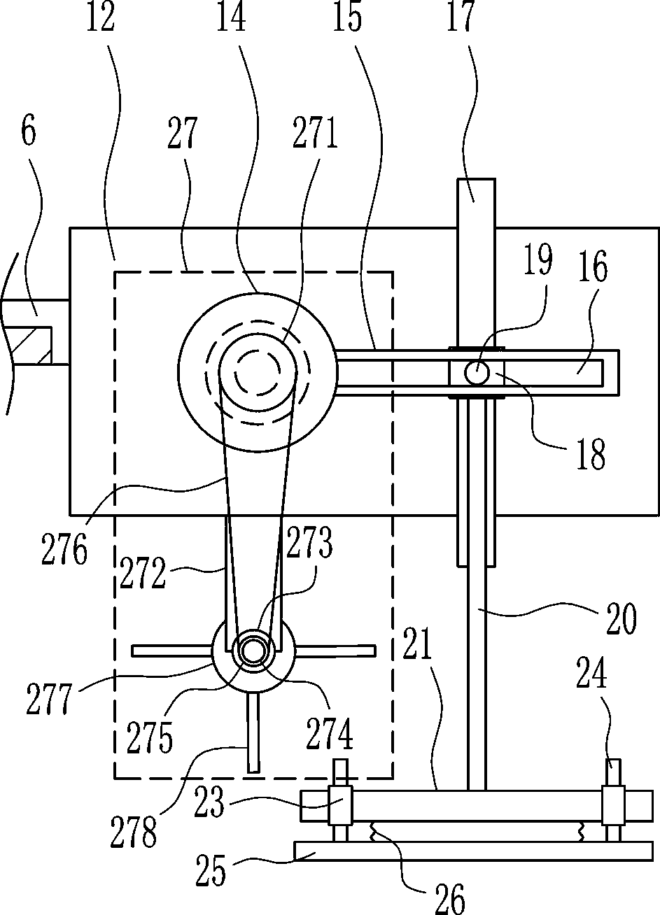
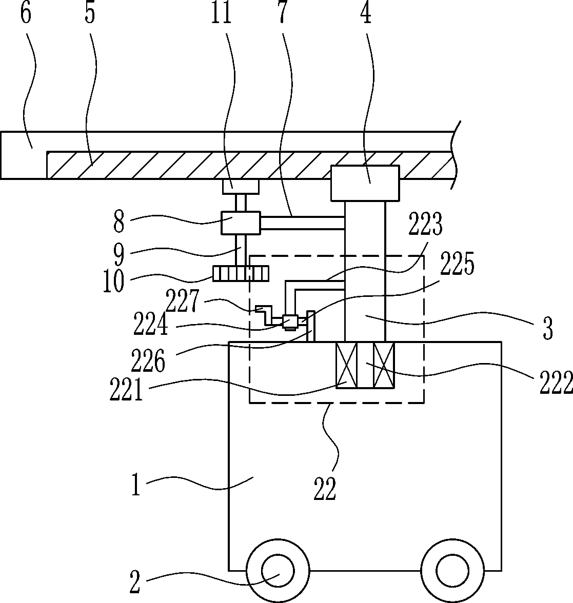
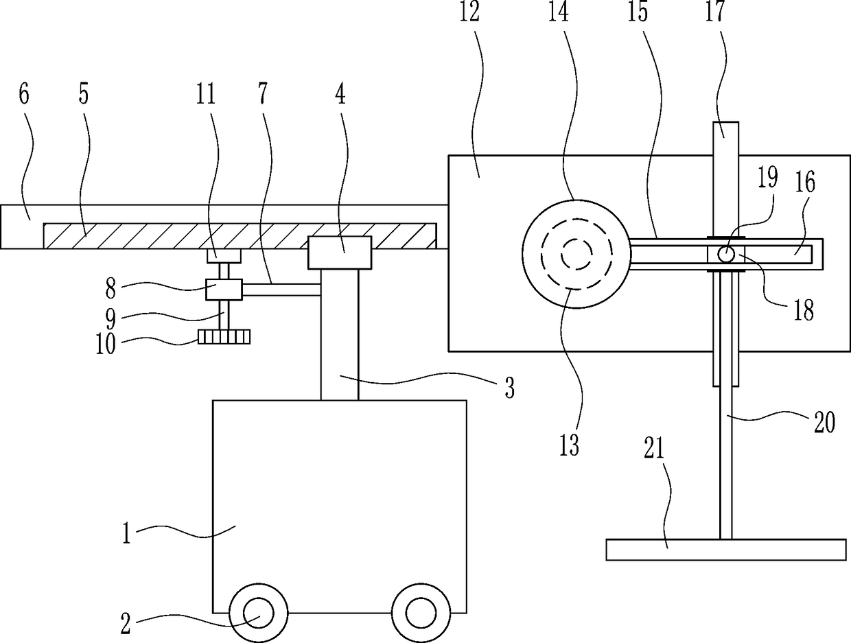
[0027] A kind of equipment for flattening after cement is laid, such as Figure 1-5As shown, it includes a base 1, a wheel 2, a support rod 3, a first slider 4, a first slide rail 5, a first connecting plate 6, a first connecting rod 7, a first nut 8, a first bolt 9, a hand Wheel 10, pressing block 11, first mounting plate 12, motor 13, disc 14, clamping plate 15, second slide rail 17, second sliding block 18, pin shaft 19, second connecting rod 20 and first pressing plate 21 , the bottom of the base 1 is provided with wheels 2, the middle of the top of the base 1 is connected with a support rod 3, the top of the support rod 3 is provided with a first slider 4, the first slider 4 is slidably provided with a first slide rail 5, and the first slide The rail 5 is provided with a first connecting plate 6, the first sliding rail 5 is embedded in the lower part of the first connecting plate 6, the upper left side of the support rod 3 is connected with the first connecting rod 7, and...

Embodiment 2

[0029] A kind of equipment for flattening after cement is laid, such as Figure 1-5 As shown, it includes a base 1, a wheel 2, a support rod 3, a first slider 4, a first slide rail 5, a first connecting plate 6, a first connecting rod 7, a first nut 8, a first bolt 9, a hand Wheel 10, pressing block 11, first mounting plate 12, motor 13, disc 14, clamping plate 15, second slide rail 17, second sliding block 18, pin shaft 19, second connecting rod 20 and first pressing plate 21 , the bottom of the base 1 is provided with wheels 2, the middle of the top of the base 1 is connected with a support rod 3, the top of the support rod 3 is provided with a first slider 4, the first slider 4 is slidably provided with a first slide rail 5, and the first slide The rail 5 is provided with a first connecting plate 6, the first sliding rail 5 is embedded in the lower part of the first connecting plate 6, the upper left side of the support rod 3 is connected with the first connecting rod 7, an...

Embodiment 3

[0032] A kind of equipment for flattening after cement is laid, such as Figure 1-5 As shown, it includes a base 1, a wheel 2, a support rod 3, a first slider 4, a first slide rail 5, a first connecting plate 6, a first connecting rod 7, a first nut 8, a first bolt 9, a hand Wheel 10, pressing block 11, first mounting plate 12, motor 13, disc 14, clamping plate 15, second slide rail 17, second sliding block 18, pin shaft 19, second connecting rod 20 and first pressing plate 21 , the bottom of the base 1 is provided with wheels 2, the middle of the top of the base 1 is connected with a support rod 3, the top of the support rod 3 is provided with a first slider 4, the first slider 4 is slidably provided with a first slide rail 5, and the first slide The rail 5 is provided with a first connecting plate 6, the first sliding rail 5 is embedded in the lower part of the first connecting plate 6, the upper left side of the support rod 3 is connected with the first connecting rod 7, an...


PUM


Abstract

The invention relates to a flattening device, in particular to a flattening device for laid cement. According to the flattening device for the laid cement, the laid cement can be flattened fast and attractively. The flattening device for laid cement comprises a base, wheels, a supporting rod, a first bolt, a handwheel, a pressing block and the like. The wheels are arranged at the bottom of the base. The supporting rod is connected to the middle of the top of the base. A first sliding block is arranged at the top of the supporting rod. A first sliding rail is arranged on the first sliding blockin a sliding mode. A first connecting plate is arranged on the first sliding rail. The first sliding rail is embedded in the lower portion of the first connecting plate. According to the flattening device for laid cement, the laid cement can be flattened fast, and the laid cement is beautiful. When the flattening device is not moved, the cement can be fast flattened everywhere. A first spring canreduce the impact force of a second pressing plate moving downwards, so that the cement can be better flattened, and the laid cement is more beautiful.

Description

technical field [0001] The invention relates to a flattening device, in particular to a flattening device after cement is laid. Background technique [0002] Cement: powdery hydraulic inorganic gelling material. In building construction, cement is widely used. For example, cement floor construction is indispensable. At present, people usually use the flattened plate to press the paved cement a little bit. Flattening, this method is not only slow in flattening the paved cement, but also the area of ​​each flattening is not large, resulting in a striated road after the cement is flattened, which affects the appearance. [0003] In summary, at present, it is necessary to develop a flattening equipment that can quickly flatten the paved cement and flatten it beautifully, so as to overcome the slow speed and unsightly flattening of the paved cement in the prior art. Shortcomings. Contents of the invention [0004] (1) Technical problems to be solved [0005] In order to ove...

Claims


Application Information

Patent Timeline
Patent Type & Authority Applications(China)
IPC IPC(8): E04F21/24
CPCE04F21/24
Inventor 黄朝仁
Owner 黄朝仁
Why Eureka
Try Eureka