
A connection structure and installation method of steel pipes for scaffolding

A technology for connecting structures and scaffolding, which is applied to the accessories of scaffolding, building structure support, building structure support, etc. It can solve problems such as poor connection strength, loose scaffolding and building walls, safety accidents, etc., and achieve simple and ingenious connection structures. The effect of installation and disassembly efficiency, installation and disassembly convenience

Active Publication Date: 2020-06-26
广东珠江工程总承包有限公司
View PDF8 Cites 0 Cited by
  • Summary
  • Abstract
  • Description
  • Claims
  • Application Information

AI Technical Summary

Problems solved by technology

There are many ways to connect rigid wall parts, but the connection strength of the current rigid wall parts is poor, and often loose or even detach between the scaffold and the building wall, causing safety accidents, so it needs to be improved

Method used


Image

  • A connection structure and installation method of steel pipes for scaffolding
  • A connection structure and installation method of steel pipes for scaffolding
  • A connection structure and installation method of steel pipes for scaffolding

Examples


Embodiment Construction

[0028] The following will clearly and completely describe the technical solutions in the embodiments of the present invention with reference to the accompanying drawings in the embodiments of the present invention. Obviously, the described embodiments are only some, not all, embodiments of the present invention. Based on the embodiments of the present invention, all other embodiments obtained by persons of ordinary skill in the art without creative efforts fall within the protection scope of the present invention.

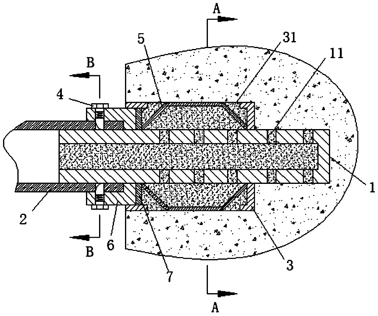
[0029] It should be noted that the nouns used to express orientation in the present invention, such as "left section", "right section", "left end", and "right end" are only for expressing the position of each technical feature more clearly, as shown in the appended figure 1 The left and right directions in the middle do not represent the only limitation on the orientation of each technical feature, and do not limit the scope of protection of the present invention. ...


PUM


Abstract

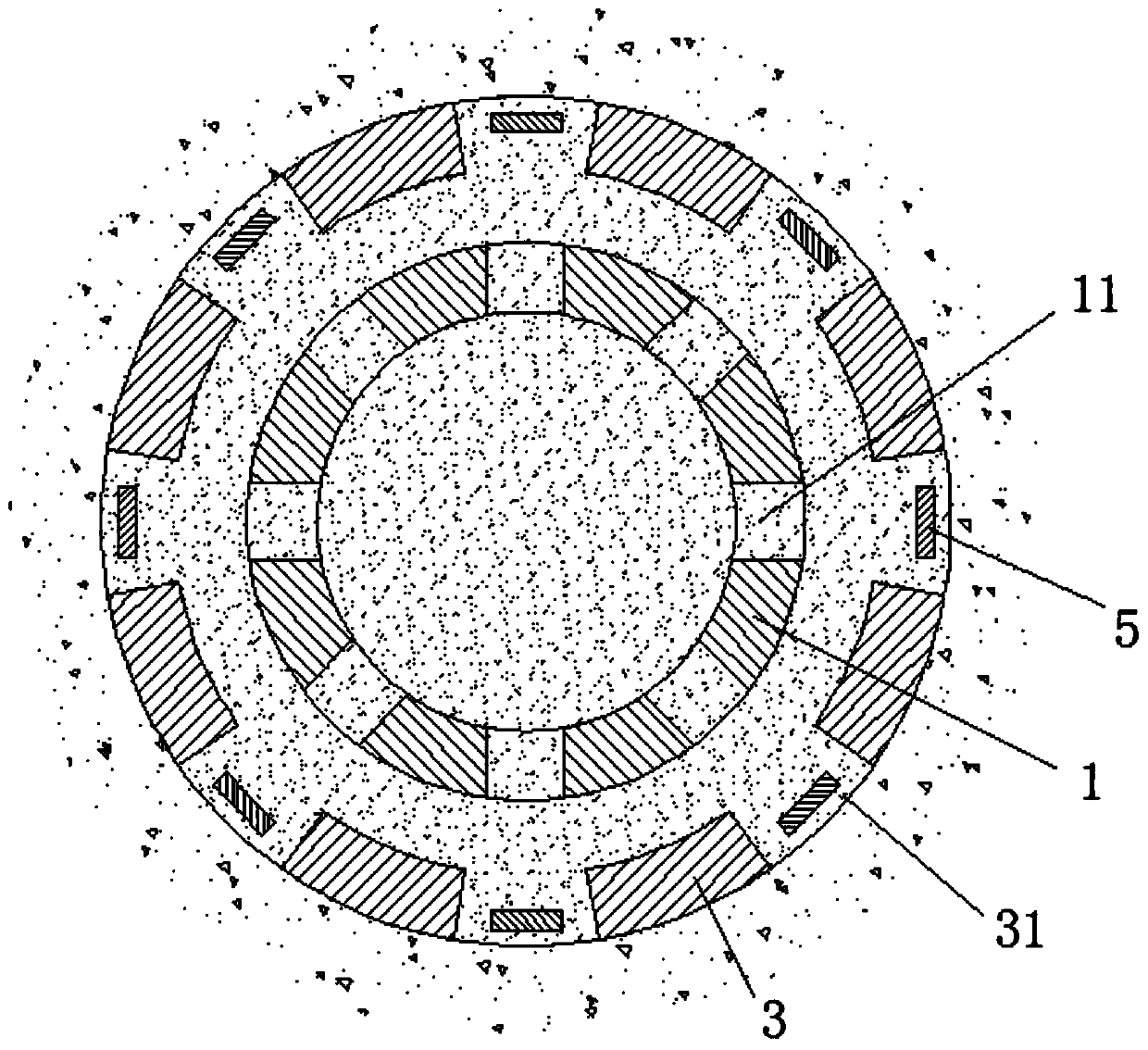
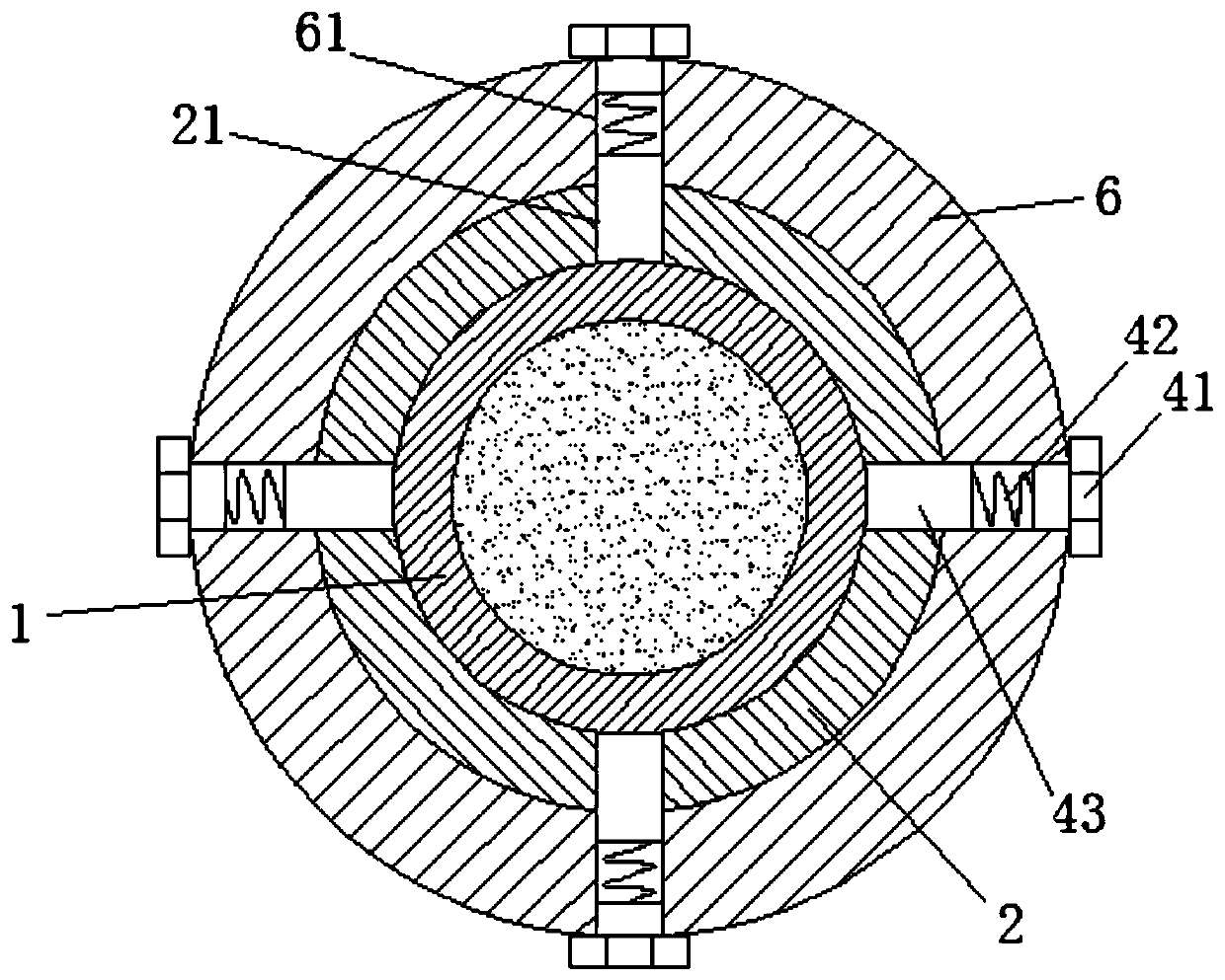
The invention relates to a connecting structure of a scaffolding steel pipe and an installation method. The connecting structure of the scaffolding steel pipe is used for connecting a scaffolding steel pipe fitting to a building wall, and includes an inner sleeve, an outer pipe, a supporting rib and a connecting sleeve. A mounting hole is formed in the building wall, the inner sleeve is inserted into the mounting hole, and the left section of the inner sleeve protrudes outwards from the mounting hole. The inner sleeve is fixedly sleeved with the outer pipe, and the outer pipe abuts against theinner wall of the mounting hole. Annular space is formed between the inner sleeve and the outer pipe, and the right end of the supporting rib is fixed to the joint of the outer pipe and the inner sleeve. The right end of the connecting sleeve is connected with the inner sleeve or the outer pipe in a threaded mode, and ringlike space is formed between the left end of the connecting sleeve and theinner sleeve. The scaffolding steel pipe fitting is inserted into the ringlike space in a sleeved mode, and the outer diameter of the connecting sleeve is not larger than the inner diameter of the outer pipe. A retreat-stopping mechanism is arranged between the scaffolding steel pipe fitting and the connecting sleeve. The connecting structure of the scaffolding steel pipe and the installation method can enable the connection between a scaffold and the wall to be more firm, and the installation is more convenient.

Description

technical field [0001] The patent of the present invention relates to a connection structure and installation method of scaffolding steel pipes. Background technique [0002] In the field of construction, in order to facilitate construction, scaffolding is usually used, and scaffolding is generally erected outside the wall. With the advancement of technology, the wall-connecting parts of scaffolding have developed from flexible wall-connecting parts to rigid wall-connecting parts. There are many ways to connect rigid wall parts, but the current rigid wall parts have poor connection strength, and often loose or even detach between scaffolding and building walls, resulting in safety accidents, so improvements are needed. Contents of the invention [0003] The invention relates to a connection structure and installation method of steel pipes for scaffolding. The scaffolding and the outer wall of a building are easy to install, firm in structure, safe and reliable. [0004] ...

Claims


Application Information

Patent Timeline
Patent Type & Authority Patents(China)
IPC IPC(8): E04G5/04
CPCE04G5/04
Inventor 郑嘉禾
Owner 广东珠江工程总承包有限公司
Learn More