The connection structure of the louver type barrier

A technology for connecting structures and louvers, applied in the directions of roads, roads, buildings, etc., can solve the problems of affecting the effect of louver components, many components required for installation, and unfavorable installation efficiency, etc., and achieves ingenious structure, simplified installation difficulty, and simple installation. Effect

Active Publication Date: 2019-12-24
HONGMEN ADVANCED TECH CORP
View PDF8 Cites 0 Cited by
  • Summary
  • Abstract
  • Description
  • Claims
  • Application Information

AI Technical Summary

Problems solved by technology

In the existing louver barriers, the main part of the sluice bar—the louver assembly is usually installed between the upper beam and the lower beam in a fixed manner, which requires many parts for installation, and the installation steps are cumbersome, which is not conducive to Improve installation efficiency
In addition, after the existing louver assemblies are installed, the louver assemblies can be relatively shaken, and the distance between the louver assemblies will change, which will affect the effect of the louver assemblies when they are lifted and folded

Method used


Image

  • The connection structure of the louver type barrier
  • The connection structure of the louver type barrier
  • The connection structure of the louver type barrier

Examples


Embodiment Construction

[0027] The following examples are further explanations and supplements to the present invention, and do not constitute any limitation to the present invention.

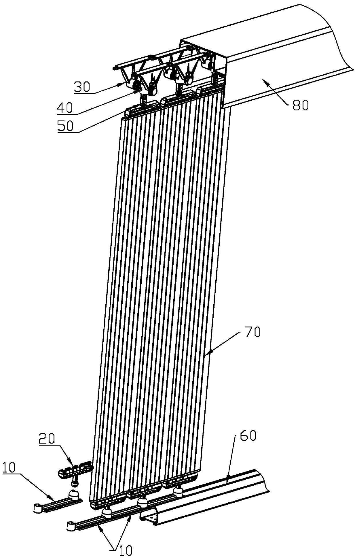
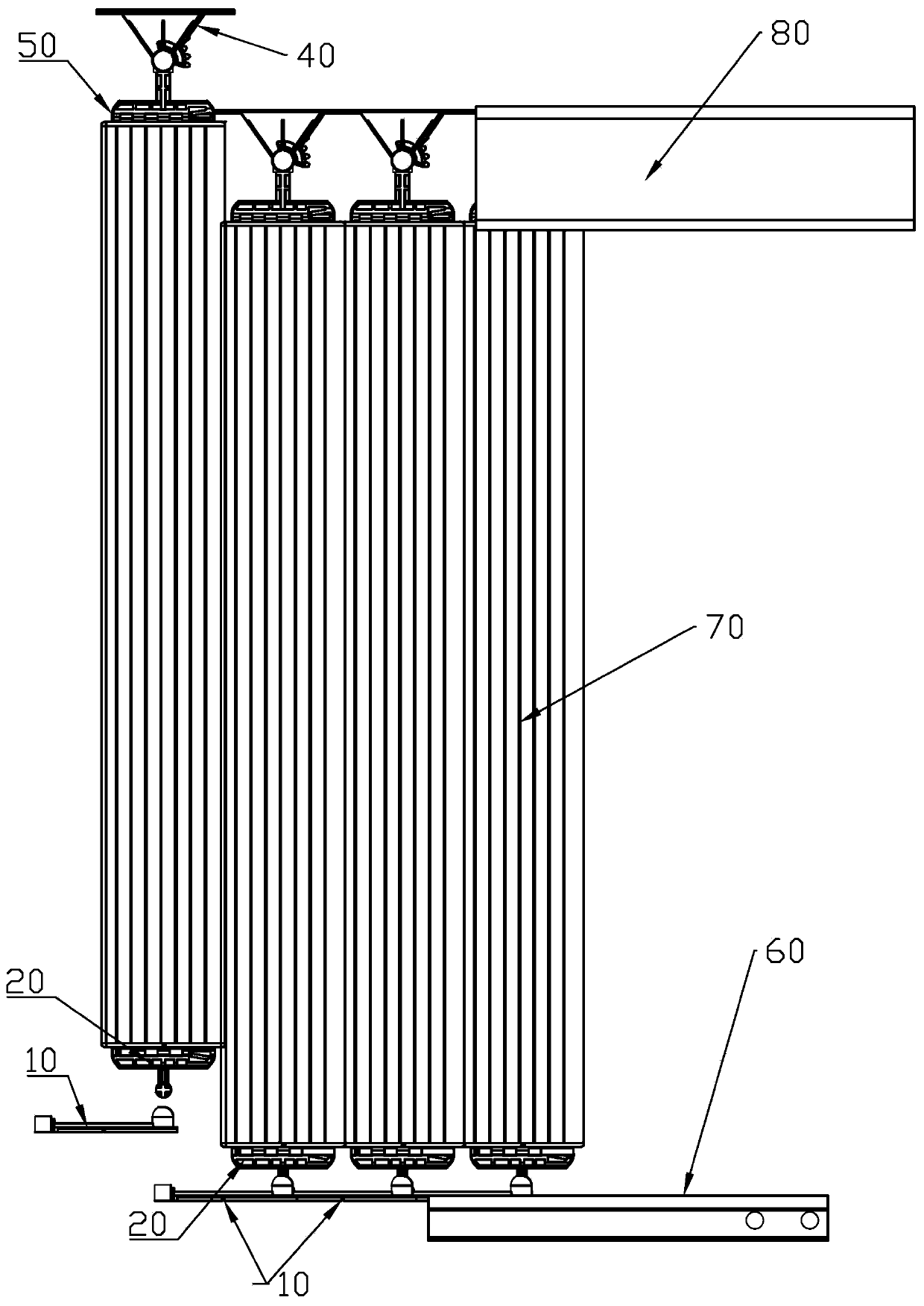
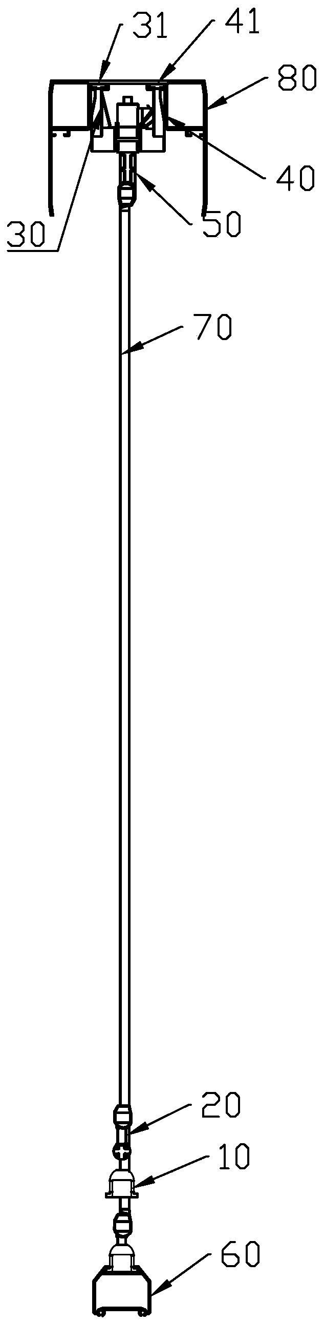
[0028] like Figure 1 to Figure 11 As shown, the main point of the connection structure of the louver-type barrier gate of the present invention is that it is connected to the beam through a single part that can be inlaid from the end to the end, so that not only can the parts required for installation be reduced, the installation difficulty is simplified, and the inlay from the end to the end It can also ensure that the distance between the installed louver blade assemblies 70 remains constant, ensuring the consistency of installation.

[0029] like Figure 1 ~ Figure 3 As shown, the connection structure of the louver type barrier of the present invention includes the connection structure of the upper beam 80 and the connection structure of the lower beam 60 . In this embodiment, the connecting structure of the low...


PUM


Abstract

A connection structure of a louvre blade type barrier gate is characterized by comprising first connection pieces which are used for being connected with a cross beam; each first connection piece comprises a first connection part in a strip shape, a protruding part and a sunken part which are integrally formed are arranged at the two ends of each first connection part correspondingly, each protruding part is provided with a containing cavity, and each sunken part is embedded in the corresponding containing cavity. When the connection structure is mounted, every two adjacent first connection pieces are connected with each other end to end through the mode that the sunken part of one first connection piece is buckled with the containing cavity of the protruding part of the other first connection piece. According to the connection structure of the louvre blade type barrier gate, the effect that the first connection pieces are connected end to end in an embedded mode is achieved by the sunken parts of the first connection pieces being inlaid into the protruding parts, accordingly mounting can be achieved only by depending on one kind of mounting parts, thus the number of the mounting parts can be decreased, the mounting difficulty is simplified, and the mounting efficiency is improved. In addition, the connection structure can further ensure that the distance between the well mounted louvre blade assemblies is constant, and thus the mounting conformity of the louvre blade assemblies is ensured.

Description

【Technical field】 [0001] The invention relates to a louver-type barrier gate, in particular to a connection structure of a louver-type barrier gate in which a louver-type barrier gate is installed on a beam of the barrier gate. 【Background technique】 [0002] Barrier gates, also known as car stoppers, are specially used in roads, residential areas, parking lots and other occasions to manage the entrance and exit of vehicles. According to the different poles of the barrier gates, the barrier gates can usually be divided into straight bar barrier gates, curved pole barrier barriers, fence barrier barriers, and louver barrier gates. The brake rod of the straight rod barrier is a straight rod, and the brake rod is straight rod in the horizontal position and the vertical position; the brake rod of the curved rod barrier is a set of curved rods, and the brake rod will move It is bent to a certain degree, and when the rod is dropped to a horizontal position, it is in the shape of ...

Claims


Application Information

Patent Timeline
Patent Type & Authority Patents(China)
IPC IPC(8): E01F13/04
Inventor 余德君文流尧李振中
Owner HONGMEN ADVANCED TECH CORP
Why Eureka
Try Eureka