High-pressure gas discharge lamp and method of manufacturing the same

A high-pressure gas, discharge lamp technology, used in the manufacture of gas discharge lamps, high-pressure discharge lamps, discharge tubes/lamps, etc.

Inactive Publication Date: 2005-08-03
KONINKLIJKE PHILIPS ELECTRONICS NV
View PDF1 Cites 2 Cited by
  • Summary
  • Abstract
  • Description
  • Claims
  • Application Information

AI Technical Summary

Problems solved by technology

This phenomenon is even more unfavorable in the case of lamps with short photoelectric arcs, since the lifetime of lamps with such electrodes is only a few hundred hours

Method used


Image

  • High-pressure gas discharge lamp and method of manufacturing the same
  • High-pressure gas discharge lamp and method of manufacturing the same
  • High-pressure gas discharge lamp and method of manufacturing the same

Examples


Embodiment Construction

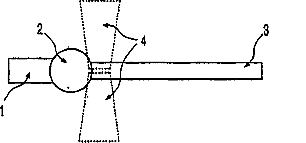
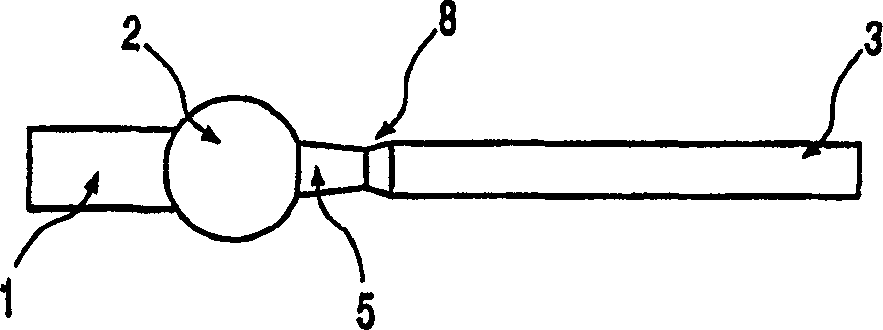
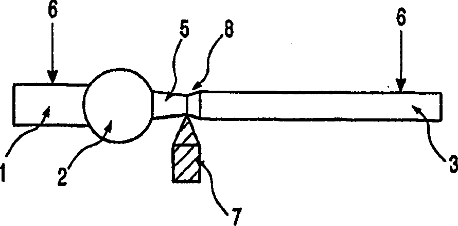
[0015] figure 1 The electrode of the high-pressure gas discharge lamp according to the invention is represented, which comprises an electrode shaft 1 whose free end extends into the discharge space and which has a widening spherical electrode head 2 . A tapered electrode protrusion is formed on this electrode head 2 in the following manner. The rod-shaped member 3 made of the same material as the electrode rod 1 is welded on the widened electrode head 2 of the electrode rod 1 by an energy source, for example with three lasers 4 , or by high-frequency heating or by a discharge arc, so that the lasers 4 Arranged around the end of the rod-shaped member 3 facing the widening electrode head 2 (i.e. viewed in a plane perpendicular to the rods 1, 3, see figure 1 ), that is, the lasers include 120° to each other. like figure 2 Said, said end of the rod-shaped member 3 is given a substantially conical shape, ie a reduced electrode protrusion 5 . The entire assembly is pressed in...


PUM


Abstract

High pressure vapor discharge lamp provided with a discharge vessel. The discharge vessel encloses a discharge space provided with a filling of mercury and a rare gas, for example, in a gastight manner. An electrode is arranged in the discharge space for generating and maintaining a discharge therein, while the electrode comprises a electrode rod (1) having an enlarged head (2) at its end which projects into the discharge space. According to the invention, the enlarged head (2) comprises a preformed electrode projection (5) having an at least substantially conical shape.

Description

technical field [0001] The invention relates to a high-pressure gas discharge lamp, a so-called HID (High Intensity Discharge) lamp or UHP (Ultra High Performance) lamp, in particular with a filling class of more than 0.05 and 0.5 mg / mm 3 between mercury vapor lamps comprising a discharge vessel enclosing a discharge space filled in a gas-tight manner with, for example, mercury and a noble gas, and comprising at least one discharge An electrode for generating and maintaining a discharge in a space, said electrode comprising an electrode rod end-ended with a widened electrode head protruding into the discharge space. The invention also relates to a method of manufacturing such a lamp. Background technique [0002] The manufacture, operating characteristics, service life and costs of such high-pressure gas discharge lamps are determined by the type and specific shape of the electrodes used. Many electrode geometries have been developed over time, taking into account to a gre...

Claims


Application Information

Patent Timeline
Patent Type & Authority Applications(China)
IPC IPC(8): H01J9/02H01J61/073H01J61/86
CPCH01J61/0732H01J61/86H01J61/073
Inventor M·J·皮埃娜
Owner KONINKLIJKE PHILIPS ELECTRONICS NV
Why Eureka
Try Eureka