
Sputtering target and method for producing same

A manufacturing method and sputtering target technology, applied in sputtering coating, vacuum evaporation coating, coating, etc., to achieve the effect of uniform axial distance, uniform thickness, and small height difference

Pending Publication Date: 2022-06-21
MITSUI MINING & SMELTING CO LTD
View PDF3 Cites 0 Cited by
  • Summary
  • Abstract
  • Description
  • Claims
  • Application Information

AI Technical Summary

Problems solved by technology

When the overall length of the target exceeds 3m, the above-mentioned problem of warping becomes more remarkable.

Method used


Image

  • Sputtering target and method for producing same
  • Sputtering target and method for producing same
  • Sputtering target and method for producing same

Examples


Embodiment

[0117] The present invention is further illustrated by the following examples. However, the following examples are not intended to limit the present invention.

[0118]

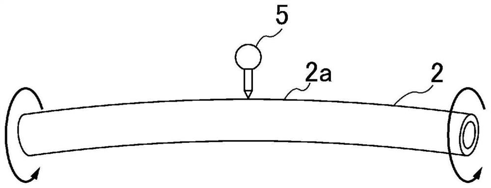
[0119] A cylindrical base material (length 3400mm, diameter 133mm, wall thickness 4mm) that is a recycled product is placed on a pedestal supported rotatably, and a dial indicator is installed horizontally and rotatably, and is suspended and fixed from above Abut the outer surface of the central part in the longitudinal direction of the cylindrical base material, make the cylindrical base material rotate once, and measure the reading of the above-mentioned dial indicator, and set the maximum value of the reading H max with the minimum value H min difference (H max -H min ) was measured as the warpage width X (initial).

[0120] Next, the cylindrical substrate was placed in an electric furnace and heated so that the surface temperature was kept at 230° C. for 1 hour, and the warpage width Y after heating...

Embodiment 2

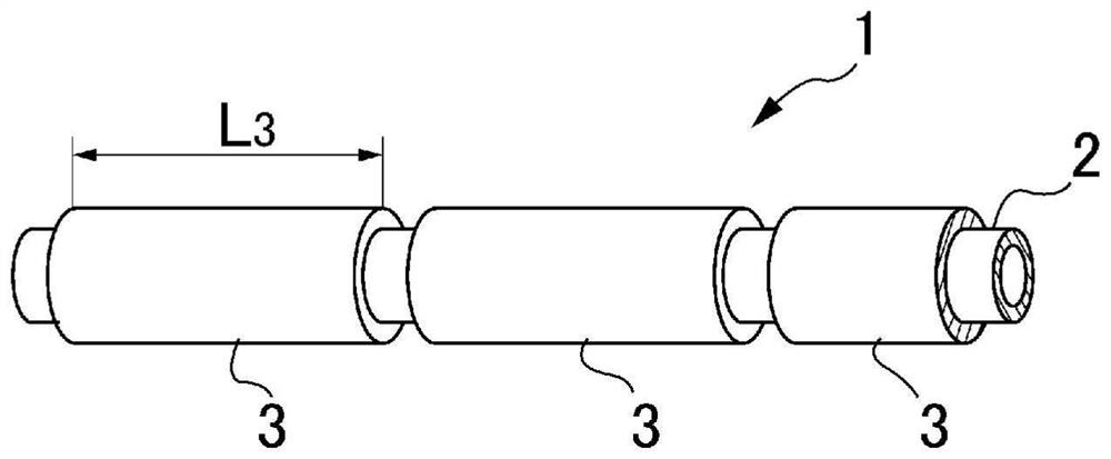
[0140] In Example 1, except having changed the longest cylindrical target material to 850 mm, it carried out similarly to Example 1, manufactured the ITO cylindrical sputtering target (sample), and measured each value.

Embodiment 3

[0142] In Example 1, except having changed the longest cylindrical target material to 1100 mm, it carried out similarly to Example 1, manufactured the ITO cylindrical sputtering target (sample), and measured each value.


PUM

PropertyMeasurementUnit
Thicknessaaaaaaaaaa
Axial lengthaaaaaaaaaa

Abstract

The present invention relates to a sputtering target capable of using a warped cylindrical base material as a constituent material, and a method for manufacturing the same, and provides a novel method for manufacturing a sputtering target in which warpage of a cylindrical base material can be eliminated even if the axial length of the cylindrical target material is long or even if the cylindrical target material is heated when being filled with a bonding material. The present invention proposes a method for manufacturing a sputtering target, which is characterized in that the degree of warping of a cylindrical base material is measured, processing is performed for warping the cylindrical base material in a direction opposite to the direction in which the cylindrical base material is warped, and a plurality of cylindrical target materials are arranged on the outside of the processed cylindrical base material at intervals in the axial direction. And bonding the cylindrical base material and the cylindrical target material with a bonding material.

Description

technical field [0001] The present invention relates to a sputtering target including a cylindrical base material and a plurality of cylindrical target materials, and a method for producing the same, and particularly relates to a sputtering target that can use a cylindrical base material that is deformed and warped as a material. Manufacturing method. Background technique [0002] In the production of organic EL, liquid crystal displays, touch panels, and other display devices, in sputtering for forming a transparent conductive thin film made of ITO or the like, a flat plate type in which a target is bonded to a flat substrate is used. Magnetron sputtering of sputtering targets is the mainstream. [0003] In recent years, rotary sputtering in which a cylindrical sputtering target in which a target material is joined to an outer peripheral surface of a cylindrical base material is rotated about an axis and sputtered has been put into practical use. According to the above-me...

Claims


Application Information

Patent Timeline
IPC IPC(8): C23C14/34C04B37/02
CPCC04B37/02C23C14/34C23C14/3407H01J37/3491H01J37/3423C04B37/026
Inventor 寺村享祐
Owner MITSUI MINING & SMELTING CO LTD
Learn More