Method for machining by lathing, and lathe

A processing device and turning technology, applied in turning equipment, positioning device, turning equipment, etc., can solve the problems of unsuitable and unsuitable turbine blades

Active Publication Date: 2012-05-30
J G WEISSER SOHNE
View PDF9 Cites 2 Cited by
  • Summary
  • Abstract
  • Description
  • Claims
  • Application Information

AI Technical Summary

Problems solved by technology

[0004] For certain workpieces, however, such turning operations are unsuitable, for example for turbine blades, which are currently generally clamped relative to an axis extending longitudinally approximately through the turbine blade and also relative to this axis movement, but the milling cutter acts on the turbine blade

Method used


Image

  • Method for machining by lathing, and lathe
  • Method for machining by lathing, and lathe
  • Method for machining by lathing, and lathe

Examples


Embodiment Construction

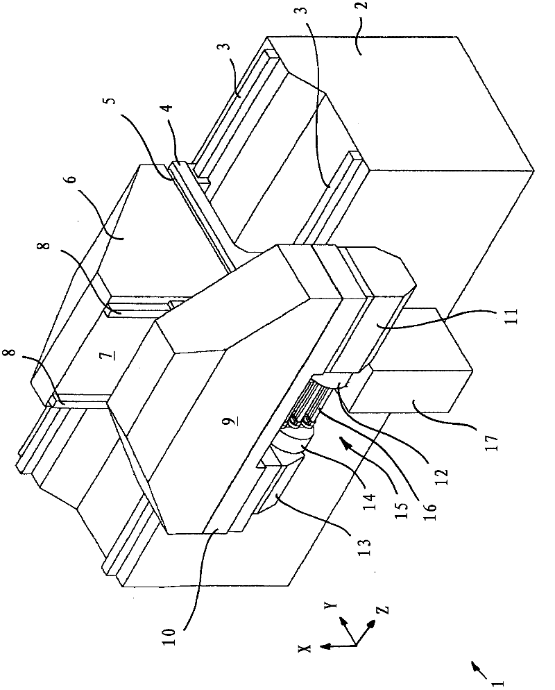
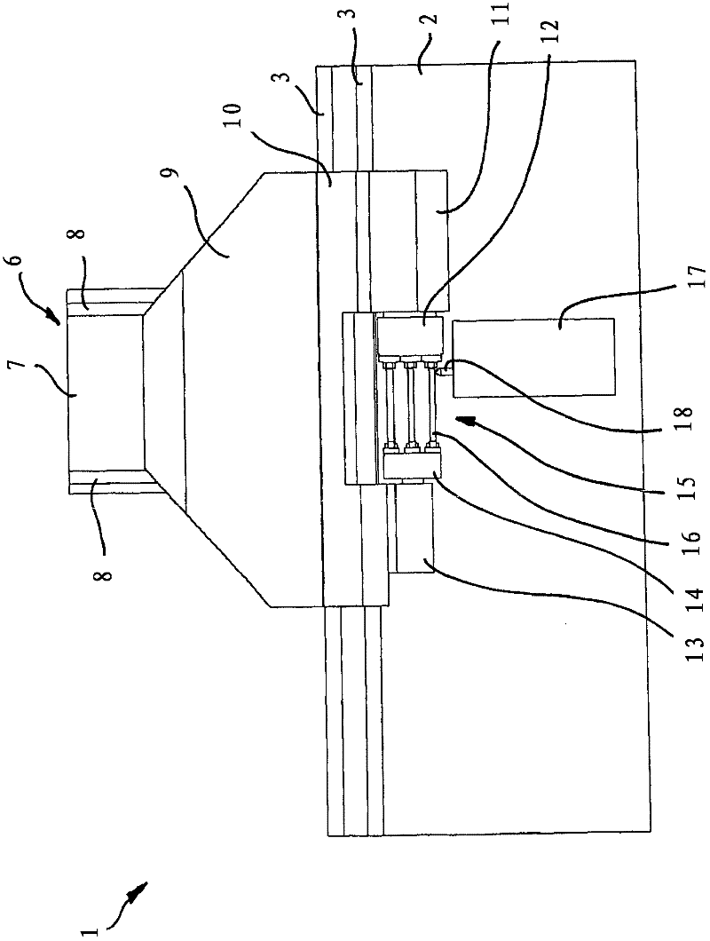
[0063] figure 1 A view from obliquely above is shown of the turning device, generally designated by the reference number 1 . figure 2 A view from the front of the turning device 1 is shown.

[0064] The turning device 1 has a bed 2 on which two horizontal linear guides 3 running in parallel are arranged. The sliding seat 4 is horizontally along the Z direction, that is, in figure 2 moves on the linear guide 3 in the plane of the drawing. The drives required for this are not otherwise shown.

[0065] Two further parallel-running and horizontally oriented linear guides 5 are arranged on the carriage 4 . exist figure 1 Only one linear guide 5 is visible. The linear guide 5 defines a movement path which is perpendicular to the movement path defined by the linear guide 3 .

[0066] A further slide 6 is arranged displaceably on the linear guide 5 , which can thus be moved along the linear guide 5 in the Y-direction by means of a drive not shown otherwise.

[0067] A furthe...


PUM


Abstract

The invention relates to a lathe (1), wherein the work piece (16) to be lathed with a tool (18) is clamped with the longitudinal axis of the work piece parallel to the rotational axis (29) of the rotating clamping device (15) such that the rotational axis (29) does not intersect the work piece (16), and that between two machining steps of the machining process by lathing, the position of the work piece (16) in the clamping device (15) is changed such that surface areas (30, 36) not previously machined are moved into the working area of the tool (18).

Description

technical field [0001] The invention relates to a method for the stock-turning machining of elongate workpieces with a longitudinal axis, which are clamped in a clamping device and rotated at a machining speed about the turning axis, wherein the turning tool for turning is transversely The infeed is infeed relative to the turning axis (in particular radially with respect to the turning axis) and / or tangentially, and the cutting speed of the turning operation is generated by the rotation of the workpiece relative to the turning tool. [0002] The invention also relates to a turning device with a clamping device driven by a turning spindle and a tool holder with a turning tool, the tool holder being transverse to the turning axis of the turning spindle (in particular radially relative to the turning axis) and / or tangentially infeed. Background technique [0003] Such methods and devices for turning workpieces are known in various forms, in which the workpiece is rotated about...

Claims


Application Information

Patent Timeline
Patent Type & Authority Applications(China)
IPC IPC(8): B23B5/18B23B5/36B23Q27/00B23P15/02
CPCB23B2265/12B23B5/18B23B5/36B23B2215/81B23Q3/063Y10T82/10Y10T82/13Y10T82/2508Y10T409/305656Y10T409/30756
Inventor T·雷蒂希R·约尔格
Owner J G WEISSER SOHNE
Why Eureka
Try Eureka