Slot cooling structure capable of improving cooling efficiency of end wall of fixed blade channel

A cooling structure and cooling efficiency technology, applied in the direction of engine components, machines/engines, mechanical equipment, etc., can solve problems such as the impossibility of cooling the front edge of the vane and the end wall near the pressure surface side, so as to prevent the intrusion of high-temperature gas and improve cooling Efficiency, safety and effective work effect

Active Publication Date: 2018-08-24
XI AN JIAOTONG UNIV
View PDF4 Cites 7 Cited by
  • Summary
  • Abstract
  • Description
  • Claims
  • Application Information

AI Technical Summary

Problems solved by technology

[0005] Aiming at the problem that the end wall of the gas turbine vane channel is subjected to extremely high heat load and the conventional method cannot effectively cool the end wall near the leading edge of the vane and the side of the pressure surface, the purpose of the present invention is to propose a method with improved vane channel end. The slot cooling structure with wall cooling efficiency, through the design of the slot cooling structure, the cooling efficiency of the front edge of the stator blade and the end wall near the pressure surface is significantly improved, thereby improving the service life of the end wall near the stator blade and ensuring the end wall near the front edge of the stator blade work safely and efficiently

Method used


Image

  • Slot cooling structure capable of improving cooling efficiency of end wall of fixed blade channel
  • Slot cooling structure capable of improving cooling efficiency of end wall of fixed blade channel
  • Slot cooling structure capable of improving cooling efficiency of end wall of fixed blade channel

Examples


Embodiment Construction

[0029]The present invention will be further described in detail below in conjunction with the accompanying drawings and technical principles. Concrete structure of the present invention sees appendix Figure 2-9 , the design idea is as follows:

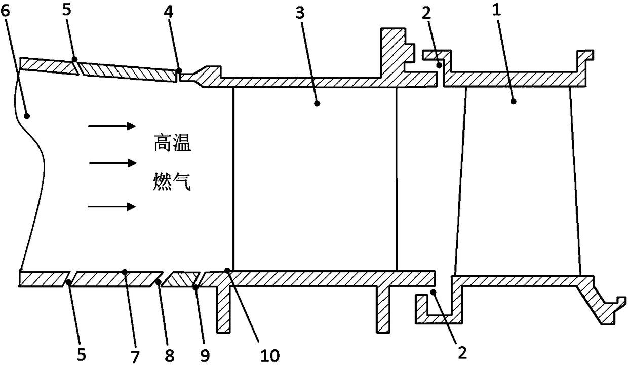
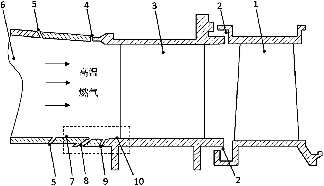
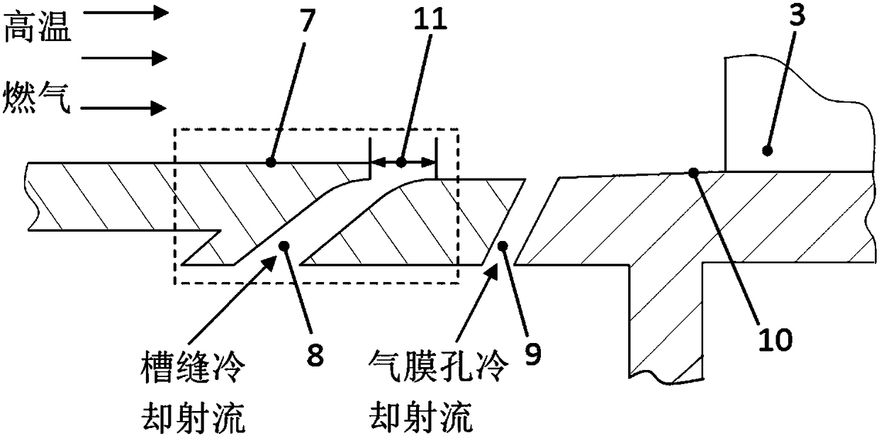
[0030] see Figure 2 to Figure 4 ,and figure 1 Compared with the traditional traditional slot cooling structure, the slot cooling structure 8 of the present invention introduces a transition fillet in the contact section between the front surface 12 of the slot cooling structure and the rear surface 13 of the slot cooling structure and the end wall 10 of the vane channel and produces The height difference H 14 between the outlet of the combustion chamber upstream of the slot and the end wall of the vane is the height of the side surface 15 of the sudden expansion step at the outlet of the combustion chamber. Wherein, the determination of the height difference H14 between the outlet of the combustion chamber and the end wall of the ...


PUM


Abstract

The invention discloses a slot cooling structure capable of improving the cooling efficiency of an end wall of a fixed blade channel. The slot cooling structure is characterized in that the radial height difference of a combustion chamber outlet end wall relative to the end wall of a fixed blade channel, and are slot structure a transition fillet structure are included; during actual gas turbine work, cooling jet flow introduced from a compressor enters a jet flow groove, the cooling jet flow is guided by the fillet structure on the contact segment of the slot and the end wall to enter the main flow area of a blade grid channel, and therefore the flowing separation of the slot cooling jet flow on a slot outlet during entering the main flow is reduced, and due to the transition fillet, whenthe slot cooling jet flow enters the main flow, the inward jetting angle is small; in addition, the relative height exists between the combustion chamber outlet end wall and the end wall of the fixedblade channel, the manual effect of the main flow and the slot cooling jet flow on the slot outlet is obviously weakened, the slot cooling jet flow can be tightly attached to the end wall to carry out sufficient cooling protection on the end wall of a downstream fixed blade channel end wall.

Description

technical field [0001] The invention relates to a slot cooling structure, in particular to a slot cooling structure between a combustion chamber of a gas turbine and a vane, which can improve the cooling efficiency of the end wall of the vane channel. Background technique [0002] As the main device for energy conversion and utilization, gas turbines are widely used in the fields of power generation, aviation, chemical industry and mechanical power. With the sharp increase of energy demand and the increasingly prominent environmental problems, the power and thermal efficiency of gas turbines have been continuously improved, which put forward stricter requirements for the design of gas turbines. In order to cope with the ever-increasing energy demand and the environmental pollution caused by energy utilization, the inlet gas temperature has been continuously increased in the development and design of gas turbines to significantly improve the thermal efficiency of the gas turb...

Claims


Application Information

Patent Timeline
Patent Type & Authority Applications(China)
IPC IPC(8): F01D25/12
CPCF01D25/12
Inventor 李军杜昆李志刚
Owner XI AN JIAOTONG UNIV
Why Eureka
Try Eureka