Hydraulic pump idle gear component

A technology of idler gears and hydraulic pumps, applied in the field of engine transmission, can solve problems affecting the service life of parts, oil leakage, wear of gear hub end faces and pressure plates, etc., and achieve the effect of reducing the difficulty of press-fitting, reducing wear and saving process time

Pending Publication Date: 2018-08-24
GUANGXI YUCHAI MASCH CO LTD
View PDF8 Cites 0 Cited by
  • Summary
  • Abstract
  • Description
  • Claims
  • Application Information

AI Technical Summary

Problems solved by technology

However, due to a certain overturning force during operation to form a rolling moment, local wear of the end face of the gear hub and the pressure plate, oil leakage and other failures often occur, seriously affecting the service life of the parts

Method used


Image

  • Hydraulic pump idle gear component
  • Hydraulic pump idle gear component
  • Hydraulic pump idle gear component

Examples


Embodiment Construction

[0021] The specific embodiments of the present invention will be described in detail below in conjunction with the accompanying drawings, but it should be understood that the protection scope of the present invention is not limited by the specific embodiments.

[0022] Unless expressly stated otherwise, throughout the specification and claims, the term "comprise" or variations thereof such as "includes" or "includes" and the like will be understood to include the stated elements or constituents, and not Other elements or other components are not excluded.

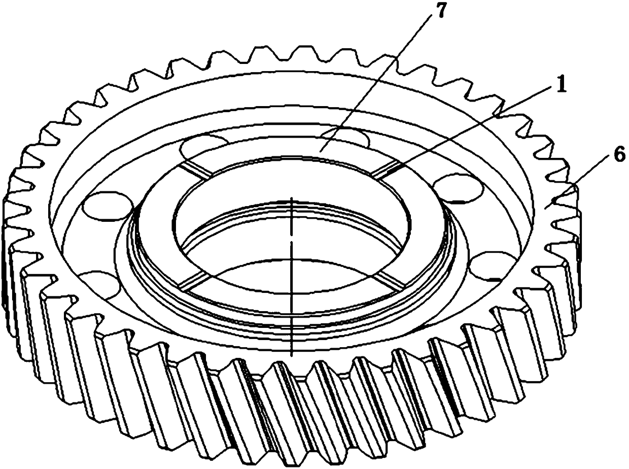
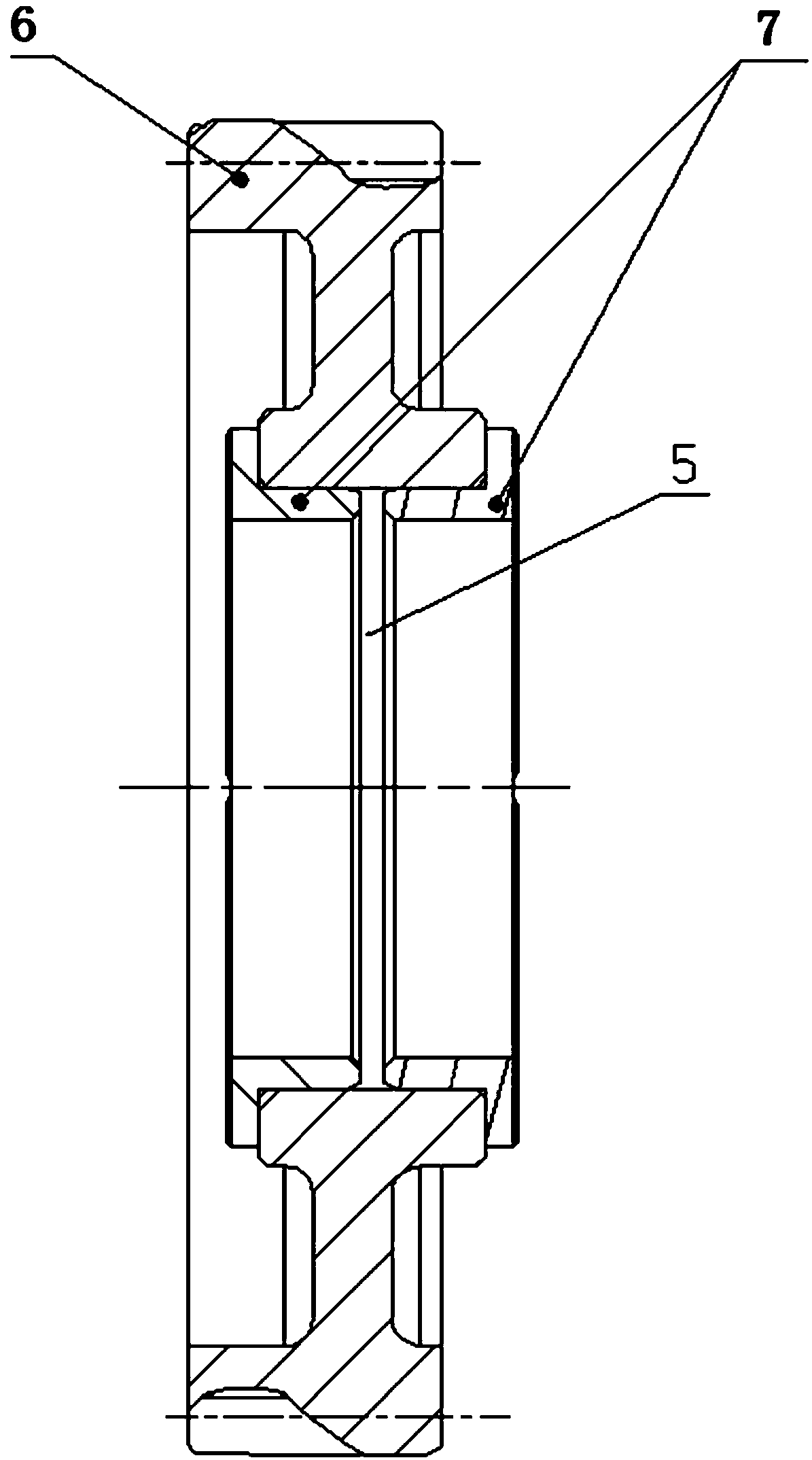
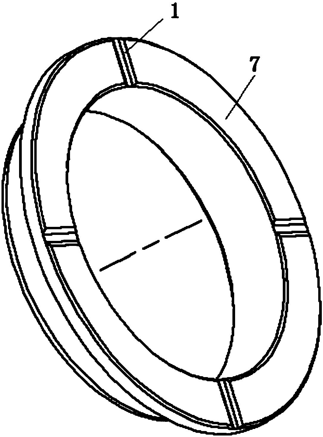
[0023] Such as figure 1 and figure 2 As shown, the specific structure of the hydraulic pump idler gear assembly according to the specific embodiment of the present invention includes: the hydraulic pump idler gear 6 and the flanging bush 7, wherein, the flanging bush 7 needs to be used in pairs, respectively from the hydraulic pump The two sides of the idler gear 6 are pressed in, and the oil drain groove structure is de...


PUM


Abstract

The invention discloses a hydraulic pump idle gear component. The hydraulic pump idle gear component comprises a hydraulic pump idle gear with a central shaft hole and flanging linings arranged in pairs, and the flanging linings comprise shaft hole inserting sleeves and flanging sides located on one ends of the shaft hole inserting sleeves. The flanging linings arranged in pairs are separately pressed both sides of the hydraulic pump idle gear through the shaft hole inserting sleeves, a plurality of oil drain slots are formed in the radial direction of the flanging sides, and installation chamfers are arranged on the outer sides of the other ends of the shaft hole inserting sleeves. An oil drain slot structure is designed on the flanging linings of the hydraulic pump idle gear component, when a gear assembly is rotated, lubricating oil can quickly cover the whole flanging side area through the oil drain slots to form an oil film, and the effects of lubrication and cooling are achieved.

Description

technical field [0001] The invention relates to the field of engine transmission, in particular to a hydraulic pump idler gear assembly. Background technique [0002] Due to the influence of factors such as installation location and lubrication conditions, the idler gear of the hydraulic pump has always been a fault-prone part. Due to the limited space, sliding bearings are generally used. However, due to a certain overturning force during operation to form a roll moment, local wear of the end face of the gear hub and the pressure plate, and failures such as oil leakage often occur, which seriously affect the service life of the parts. [0003] The information disclosed in this Background section is only for enhancing the understanding of the general background of the present invention and should not be taken as an acknowledgment or any form of suggestion that the information constitutes the prior art that is already known to those skilled in the art. Contents of the inve...

Claims


Application Information

Patent Timeline
Patent Type & Authority Applications(China)
IPC IPC(8): F16H55/17F16H55/12F16H57/04
CPCF16H55/12F16H55/17F16H57/0412F16H57/0427
Inventor 张振坤梁保权吴定勇苏怀林刘显宏韩柳林振丽
Owner GUANGXI YUCHAI MASCH CO LTD
Why Eureka
Try Eureka