Feeding device for can lid pressing process

A technology of feeding device and pressing device, which is applied in the field of tea cans, can solve the problems of inability to form, high error rate of workers, hidden safety hazards, etc., and achieve the effect of light weight

Active Publication Date: 2019-09-03
ANHUI YILIANG TANK IDUSTRY TECH CO LTD
View PDF14 Cites 0 Cited by
  • Summary
  • Abstract
  • Description
  • Claims
  • Application Information

AI Technical Summary

Problems solved by technology

[0002] In the field of tea production, iron cans are often used to hold tea. The lids of iron cans often need to use pressing machines during processing. The raw iron sheets are placed on the bottom mold of the pressing machine, and the iron sheets are pressed into specific The traditional pressing method is that the workers sit in front of the pressing machine, control the pressing switch with their feet, take out the strip-shaped iron sheet with both hands, put the iron sheet under the die head, put their hands on both sides of the die head, and step on it with their feet. Press the switch, press the die head down to press the iron sheet, then take out the can lid and move the iron sheet to one side for a certain distance, step on the switch again to complete the pressing, and repeat the pressing operation according to this method. In the traditional pressing process, in order to ensure that the iron sheet Raw material utilization rate, when the iron sheet raw material is cut into strips, its width should be as small as possible after taking into account the side of the can lid. A complete circle, long-term operation leads to high error rate of workers, and workers need to cooperate with their hands and feet when pressing, and start the machine with their feet after each moving the iron sheet. The pressing process is short, and the hands are always near the die head, repeating the operation for a long time It is easy to cause muscle soreness of workers and cause safety hazards

Method used


Image

  • Feeding device for can lid pressing process
  • Feeding device for can lid pressing process
  • Feeding device for can lid pressing process

Examples


Embodiment Construction

[0016] Preferred embodiments of the present invention will be described in detail below in conjunction with the accompanying drawings.

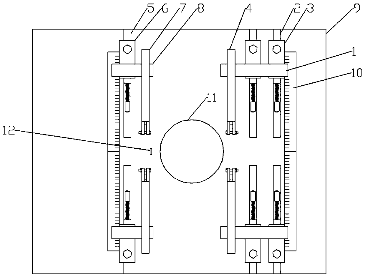
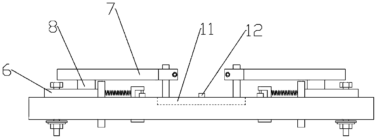
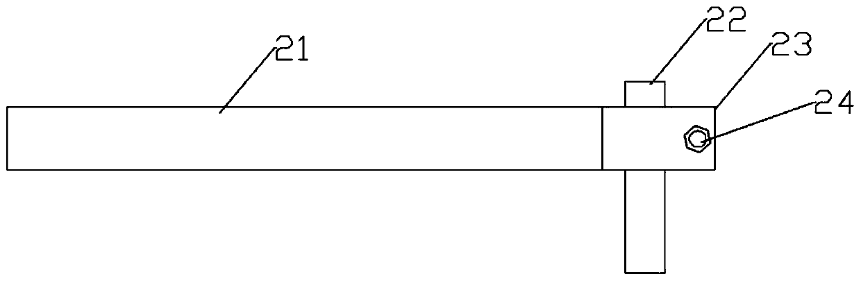
[0017] Figure 1-5 The specific embodiment of the present invention is shown: a feeding device for the can lid pressing process, including a workbench 9, a bottom mold 11 and a thin elastic sheet 12 are arranged in the center of the worktable 9, and each time the thin elastic sheet 12 is dumped, it stops moving and performs pressing operation, and the distance between the two pressings is judged by the thin shrapnel 12. The bottom mold 11 is provided with four symmetrical chute 1 on one side and two symmetrical chute 2 5 on the other side. The groove one 2 is provided with a rolling device one 3, the said chute two 5 is provided with a rolling device two 6, said rolling device one 3 is provided with a pole one 1, and said pole one 1 upper end is provided with a pressing Device one 4, the rolling device two 6 is provided with a pole two 8, th...


PUM


Abstract

The invention discloses a feeding device for a canister cover pressing working procedure. The feeding device for the canister cover pressing working procedure comprises a workbench. The center of theworkbench is provided with a bottom die and a thin elastic piece. One side of the bottom die is provided with four symmetrical first sliding grooves, and the other side of the bottom die is provided with two symmetric second sliding grooves. The first sliding grooves are internally provided with first rolling devices. The second sliding grooves are internally provided with second rolling devices.The first rolling devices are provided with first fulcrum bars, and the upper ends of the first fulcrum bars are provided with first pressing devices. The second rolling devices are provided with second fulcrum bars, and the upper ends of the second fulcrum bars are provided with second pressing devices. According to the feeding device for the canister cover pressing working procedure, correct positioning is firstly carried out when an iron sheet enters the upper end of the bottom die, and therefore the width of the iron sheet is reduced; and the distance between two times of pressing is judged through the thin elastic sheet, the utilization rate of the iron sheet is higher, the operation level of workers is reduced, meanwhile, during operation, only one hand is needed and is far away fromthe bottom die, potential safety hazards can be effectively eradicated, and the situation that the iron sheet deviates, and consequentially the edge of a canister cover cannot be pressed in place isalso avoided.

Description

technical field [0001] The invention relates to the field of tea cans, in particular to a feeding device for the pressing process of can lids. Background technique [0002] In the field of tea production, iron cans are often used to hold tea. The lid of the iron can often needs to use a pressing machine during processing. The raw iron sheet is placed on the bottom mold of the pressing machine, and the iron sheet is pressed into a specific The traditional pressing method is that the worker sits in front of the pressing machine, controls the pressing switch with his feet, takes out the strip-shaped iron sheet with both hands, puts the iron sheet under the die head, puts his hands on both sides of the die head, and steps on it with his feet. Press the switch, press the die head down to press the iron sheet, then take out the can lid and move the iron sheet to one side for a certain distance, step on the switch again to complete the pressing, and repeat the pressing operation in...

Claims


Application Information

Patent Timeline
Patent Type & Authority Patents(China)
IPC IPC(8): B21D51/44B21D43/09B21D22/02
CPCB21D22/02B21D43/09B21D51/446
Inventor 邢永义邢婷王伟
Owner ANHUI YILIANG TANK IDUSTRY TECH CO LTD
Why Eureka
Try Eureka