Upper vehicle-body structure of vehicle

A vehicle body and vehicle technology, which is applied to the superstructure, vehicle components, and superstructure sub-assemblies, etc., can solve the problems of reduced load transmission, reduced passenger space, and increased load, so as to suppress shape deformation and prevent rigidity from decreasing. , the effect of improving rigidity

Active Publication Date: 2018-08-28
MAZDA MOTOR CORP
View PDF8 Cites 5 Cited by
  • Summary
  • Abstract
  • Description
  • Claims
  • Application Information

AI Technical Summary

Problems solved by technology

[0005] However, according to the vehicle body structure disclosed in the above-mentioned Patent Document 1, when a predetermined load or more is input from the side of the vehicle, such as an impact load during a side collision, even if the center pillar can be prevented from entering the passenger compartment largely, the When the upper part of the center pillar is displaced to the vehicle interior, the lower part of the roof side rail also rotates so as to wrap around the vehicle interior, and by this rotation, the joint part of the roof reinforcement is lifted upward via the gussets. Bending moment is generated in the direction of the load, and the amount of load transmitted to the roof side rail and the center pillar on the side where the load is not input decreases, so the load input to the door and the vehicle body components adjacent in the front-rear direction of the door increases.
Therefore, although some countermeasures have been taken to increase the strength of the door and the vehicle body components adjacent to the door in the front-rear direction, there is still room for improvement in the load transmission via the roof reinforcement.
[0006] Therefore, in order to improve the load transmission via the roof reinforcement, as a means to prevent the roof reinforcement from deforming upward, the thickness of the roof reinforcement is increased, or the cross-section is enlarged in the front-rear direction or the vertical direction of the vehicle body, thereby increasing the thickness of the roof reinforcement. Greater rigidity of the roof reinforcement, but this may result in increased vehicle weight or reduced passenger space

Method used


Image

  • Upper vehicle-body structure of vehicle
  • Upper vehicle-body structure of vehicle
  • Upper vehicle-body structure of vehicle

Examples


Embodiment Construction

[0038] Hereinafter, the upper body structure of the vehicle according to the embodiment of the present invention will be described in detail.

[0039] In addition, the upper body structure on the right side of the vehicle shown in the drawings will be described below, but the upper body structure on the left side of the vehicle is also the same as the upper body structure on the right side of the vehicle.

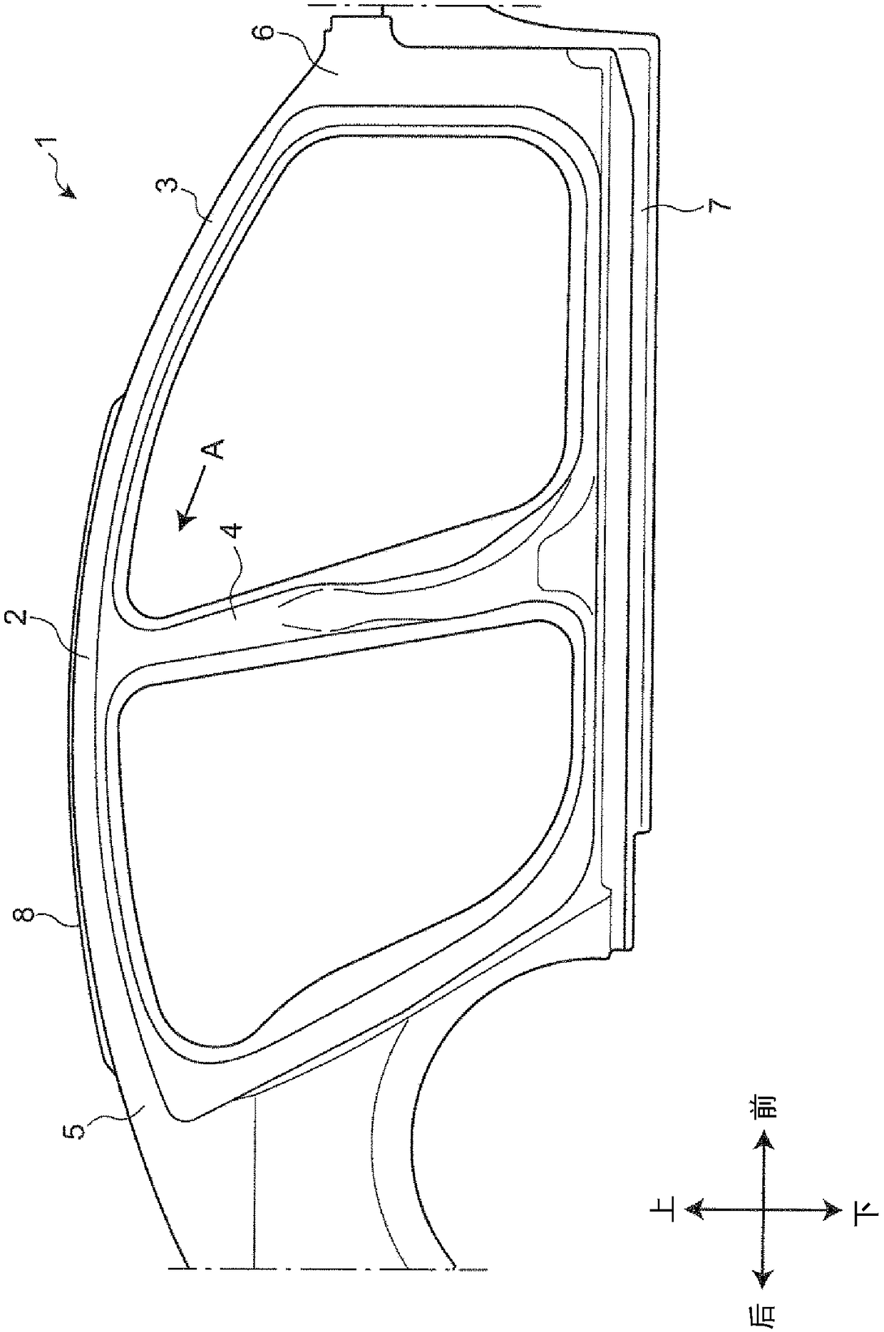
[0040] Such as figure 1 As shown, on the side portion of the vehicle body 1, a roof side rail portion 2 extending in the front-rear direction of the vehicle body is provided on the upper portion, and the front pillar portion 3 is connected to the front end portion of the roof side rail portion 2, and is connected to the center portion. The center pillar portion 4 is connected to the rear pillar portion 5 at the rear end.

[0041] At the front end of the front pillar part 3, the upper end of the hinge pillar part 6 extending up and down is connected. At the lower end of the...


PUM


Abstract

Provided is an upper vehicle body structure; when a preset load is inputted from the vehicle side, the structure can suppress the central pillar from largely entering the cabin, thus preventing roof enforcement deformation, and effectively diffusing regular loads inputted on the vehicle body onto the roof enforcement. In a vehicle-body (1) structure in which a roof side rail portion (2) of a sideface portion of a vehicle body and the roof reinforcement (9) are connected via a gusset (G) so as to suppress that the center pillar portion comes into a cabin side when the large load is inputted from a vehicle side, wherein a notch portion (G17) is provided at the gusset. Thereby, it is suppressed that, when the large load is inputted to the center pillar portion (4) from the vehicle side, thegusset (G) is so bending-deformed by a rotation of the roof side rail portion (2) that a rotational moment m caused by the rotation of the roof side rail portion (2) acts on the roof reinforcement (9), suppressing that the center pillar portion (4) comes into the cabin side.

Description

technical field [0001] The present invention relates to an upper body structure of a vehicle in consideration of a predetermined or greater load input from the side of the vehicle, and belongs to the technical field of body structures of vehicles. Background technique [0002] As the upper body structure of the vehicle, Patent Document 1 discloses a vehicle body structure comprising: left and right center pillars provided on the side portions of both sides of the vehicle; The upper part extends in the front-rear direction of the vehicle, and the roof reinforcement is arranged at the same position as the center pillar in the front-rear direction of the vehicle body, and connects the left and right roof side rails in the vehicle width direction. [0003] In addition, in the vehicle body, gussets are installed across the roof reinforcement and the roof side rails, so that the load input to the center pillar from the side of the vehicle is transmitted to the roof reinforcement t...

Claims


Application Information

Patent Timeline
Patent Type & Authority Applications(China)
IPC IPC(8): B62D25/06B62D25/04
CPCB62D25/04B62D25/06B62D21/157B62D25/02B62D27/023
Inventor 吉武晃司古贺俊之门畑智大
Owner MAZDA MOTOR CORP
Why Eureka
Try Eureka