Rotatable automatic spraying mechanism

A technology of automatic spraying and main rotation, applied in the direction of building structure, construction, etc., can solve the problems of automatic painting, human injury, hard to find, etc., and achieve the effect of easy implementation, better effect, and good anti-clogging effect.

Active Publication Date: 2018-08-28
广州伯乐智能技术有限公司
View PDF8 Cites 6 Cited by
  • Summary
  • Abstract
  • Description
  • Claims
  • Application Information

AI Technical Summary

Problems solved by technology

In the construction industry, the current main working method is manual operation. For grouting and painting operations, manual painting is required. This kind of work needs to test the technical level of the operator, especially for the ratio of cement or paint. Dilution and selection are a test of the operator's skills. For experienced operators, it takes long-term training and exercise to be able to operate independently. The demand is large; on the other hand, there will be dust or chemical substances inhaled into the human body by manual brushing or painting, which will be harmful to the human body
Existing robots cannot yet handle automatic grouting and automatic modeling of rooms Automatic grouting, or automatic painting
[0003] The nozzle structure of automatic spraying is mostly fixed, or the direction of rotation is single, and the existing rotary nozzle cannot be used in combination with this automatic painting device

Method used


Image

  • Rotatable automatic spraying mechanism
  • Rotatable automatic spraying mechanism
  • Rotatable automatic spraying mechanism

Examples


Embodiment 1

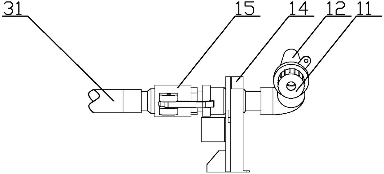
[0028] refer to figure 1 , a rotary automatic spraying mechanism, including a spray head assembly, a main conduit 13, a support frame 14, a main rotary connector 15, a main drive motor 16 and a controller, the spray head assembly includes a nozzle 11 and an air pipe coaxial with the nozzle 11 Joint 12, the main conduit 13 is connected to the nozzle 11, and an angle is formed between the axis of the main conduit 13 and the axis of the nozzle 11, and one end of the main conduit 13 is connected to the main rotary connector 15, the main rotary connector 15 is fixedly connected to the support frame 14, the main drive motor 16 is connected to the support frame 14, a gear is sleeved on the main pipe 13, and the main drive The motor 16 is connected to the main conduit 13 through gears;

[0029] The main drive motor 16 is electrically connected to the controller.

[0030] A feed pipe 31 is connected to said main rotary connection 15 .

Embodiment 2

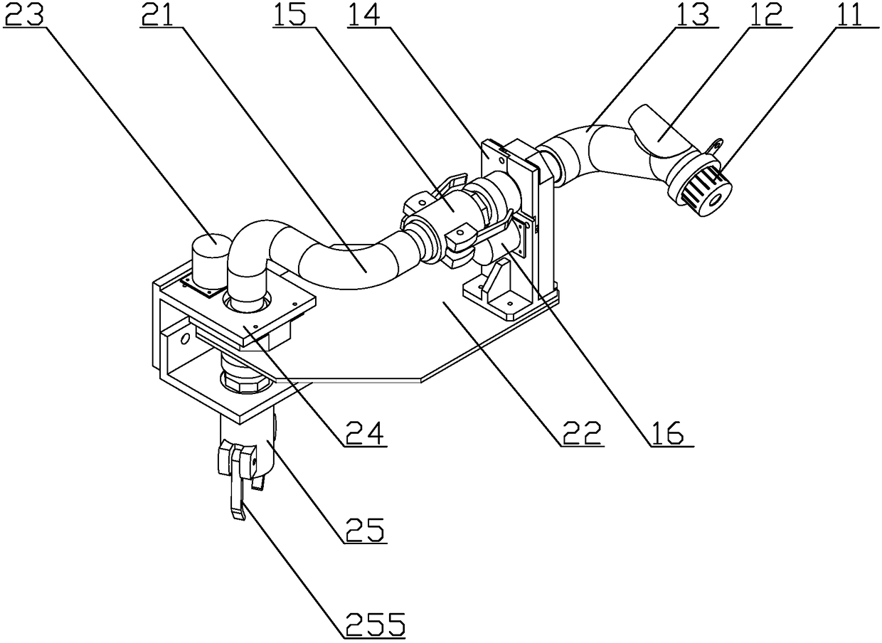
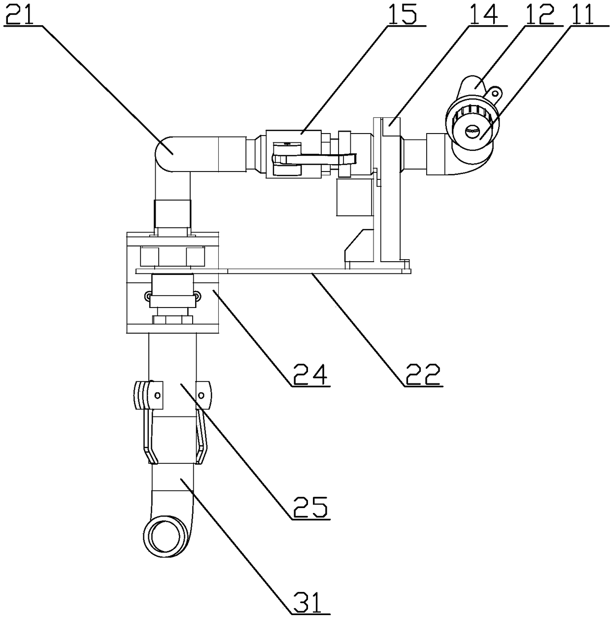
[0032] refer to figure 2 and image 3 , a rotary automatic spraying mechanism, including a spray head assembly, a main conduit 13, a support frame 14, a main rotary connector 15, a main drive motor 16 and a controller, the spray head assembly includes a nozzle 11 and an air pipe coaxial with the nozzle 11 Joint 12, the main conduit 13 is connected to the nozzle 11, and an angle is formed between the axis of the main conduit 13 and the axis of the nozzle 11, and one end of the main conduit 13 is connected to the main rotary connector 15, the main rotary connector 15 is fixedly connected to the support frame 14, the main drive motor 16 is connected to the support frame 14, a gear is sleeved on the main pipe 13, and the main drive The motor 16 is connected to the main conduit 13 through gears;

[0033] The main drive motor 16 is electrically connected to the controller.

[0034] Such as Figure 4 , the present invention also includes a supporting rotating plate 22, an auxili...


PUM


Abstract

The invention discloses a rotatable automatic spraying mechanism which comprises a sprayer component, a main guide pipe, a supporting frame, a main rotating connector, a main driving motor and a controller. The sprayer component comprises a sprayer and an air pipe joint coaxial with the sprayer, the main guide pipe is connected with the sprayer, an included angle is formed between an axis of the main guide pipe and an axis of the sprayer, one end of the main guide pipe is connected with the main rotating connector, the main rotating connector is fixedly connected on a supporting frame, the main driving motor is connected on the supporting frame, a gear is connected on the main guide pipe in a sleeving manner, and the main driving motor is connected on the main guide pipe through the gear and electrically connected with the controller. The spraying mechanism is simple in structure and easy to implement and can rotate 360 degrees, so that integrated stereoscopic space is rotatably sprayed, the spraying mechanism and a robot are matched and used, and effects are better.

Description

technical field [0001] The invention relates to the field of building surface spraying, in particular to an indoor automatic spraying and grouting device. Background technique [0002] With the advancement and development of intelligent technology, the requirements for intelligence in all walks of life are constantly increasing. In the construction industry, the current main working method is manual operation. For grouting and painting operations, manual painting is required. This kind of work needs to test the technical level of the operator, especially for the ratio of cement or paint. Dilution and selection are a test of the operator's skills. For experienced operators, it takes long-term training and exercise to be able to operate independently. The demand is large; on the other hand, whether it is manual brushing or painting, dust or chemical substances will be inhaled into the human body, which is harmful to the human body. Existing robots cannot yet handle automatic...

Claims


Application Information

Patent Timeline
Patent Type & Authority Applications(China)
IPC IPC(8): E04F21/08
CPCE04F21/08
Inventor 叶博森李伯基文哲
Owner 广州伯乐智能技术有限公司
Why Eureka
Try Eureka