Ceiling fan

A fan and ceiling technology, which is applied in the field of ceiling fans, can solve the problems of small coverage and inability to circulate air, and achieve the effect of reducing dust accumulation on the wind wheel

Pending Publication Date: 2018-08-28
AUPU HOME STYLE CORP LTD
View PDF5 Cites 4 Cited by
  • Summary
  • Abstract
  • Description
  • Claims
  • Application Information

AI Technical Summary

Problems solved by technology

[0004] The technical problem to be solved and the technical task proposed by the present invention are to overcome the defects of the existing ceiling fan that the blades are easy to stick ash and the coverage area is small, and the airflow cannot circulate the entire space, and to provide a ceiling fan

Method used


Image

  • Ceiling fan
  • Ceiling fan
  • Ceiling fan

Examples


Embodiment Construction

[0034] The present invention will be further described below in conjunction with the accompanying drawings of the description.

[0035] Such as Figure 1-3 Ceiling fans shown, including:

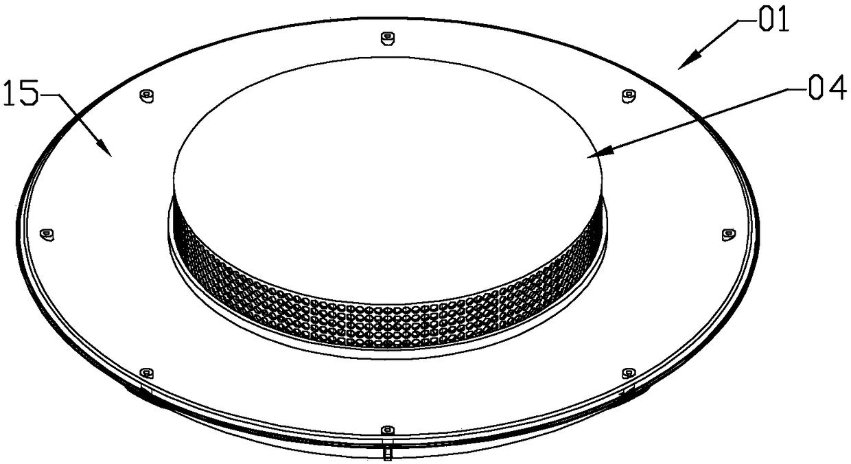
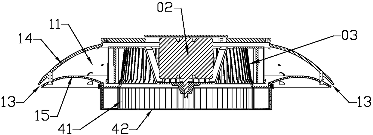
[0036] The circular housing 01 has a circular accommodation chamber 11 inside, and its outer peripheral edge has an annular slit facing downwards (the orientation is determined by the installation and use state, the same below) as the air outlet 12, and the center of the lower end has a through hole as the air outlet. The air inlet 13, the air outlet 12, and the air inlet 13 are connected to the circular accommodation chamber 11;

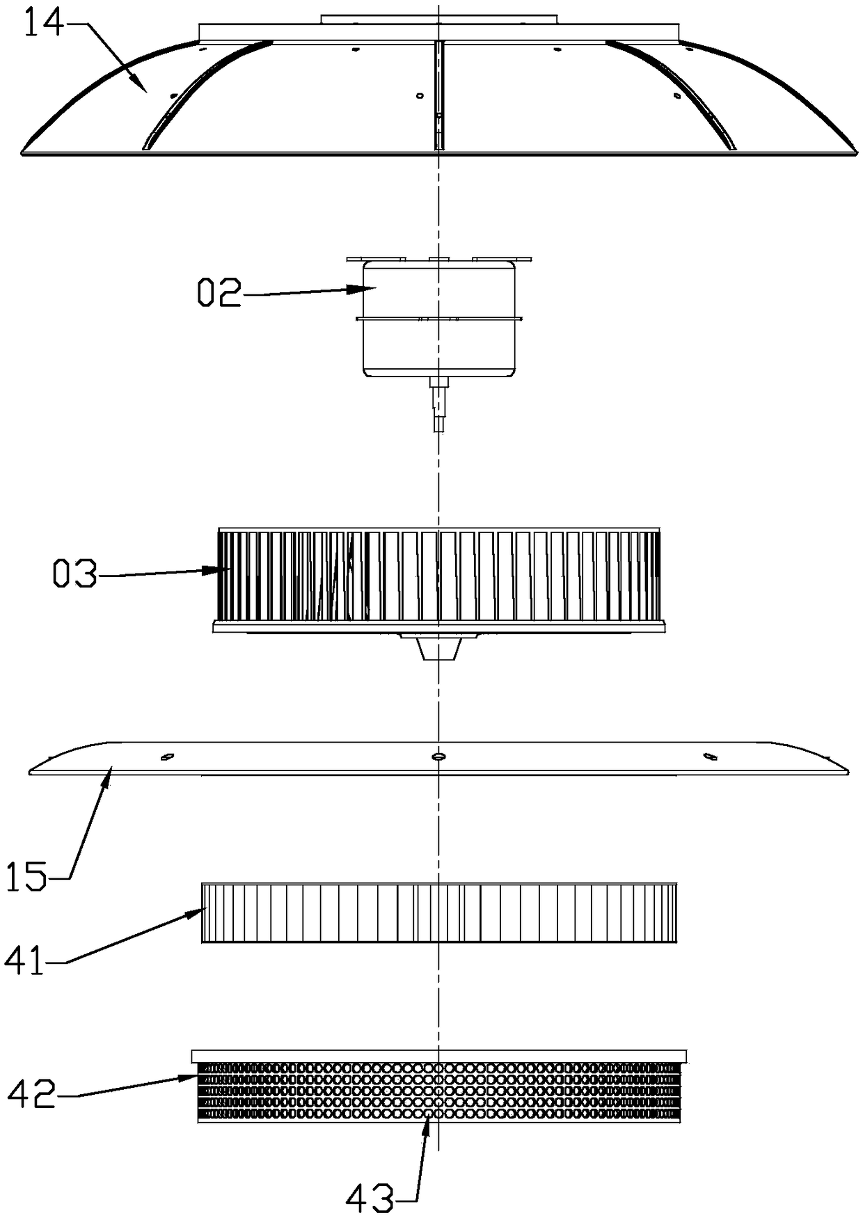
[0037] Motor 02, which is located in the circular accommodation cavity and fixedly assembled on the housing (specifically, assembled on the inside of the first wind deflector 14 mentioned below), and its output shaft extends downward;

[0038] Image 6 The centrifugal wind wheel 03 shown is located in a circular housing chamber, with an air suction port facing ...


PUM


Abstract

The invention discloses a ceiling fan, and belongs to electric fans. An existing ceiling blade fan blade is prone to ash adhering, the coverage range is narrow, and airflow cannot circulate in the whole space. An annular slit facing the surrounding lower portion is arranged in a shell to serve as an air outlet, during work, 360-degree annular air outflow is formed, the airflow coverage range is wide, and air of the whole space can be promoted to circulate. Meanwhile, a wind wheel is located in the shell, a filter device shielding an air inlet is assembled at the air inlet position of the shell, wind wheel accumulated dust is reduced, meanwhile, blown air is clean, and the purification function is achieved for indoor air. Furthermore, an LED lamp can be arranged in a circular containing cavity of the shell, and the fan and the LED lamp are integrated. Meanwhile, the heat dissipation and lighting functions are achieved, the ceiling fan can serve as a heat dissipation substitute product when an air conditioner is not needed, the indoor air circulates, and the purposes of air purification and heat dissipation are achieved.

Description

technical field [0001] The invention belongs to a fan, in particular to a ceiling fan. Background technique [0002] The fan is an electrical appliance for heat dissipation in summer. In the past, the ceiling fan was driven by an internal motor, and the rotation of the blades promoted air circulation to achieve the purpose of heat dissipation. However, the exposed ceiling fan blades are easy to stick to the dust, and the dust will be blown away when it is turned on, causing the indoor air to be turbid, and the coverage is small, and the airflow cannot circulate the entire space. [0003] In addition, the position where the fan is installed often needs to be installed with a lighting lamp due to lighting requirements, while most of the ceiling fans in the past have no lighting function. Contents of the invention [0004] The technical problem to be solved and the technical task proposed by the present invention are to overcome the disadvantages of the existing ceiling fan ...

Claims


Application Information

Patent Timeline
Patent Type & Authority Applications(China)
IPC IPC(8): F04D25/08F04D29/42F04D29/70F21V33/00F21Y115/10
CPCF04D25/088F04D29/4226F04D29/703F21V33/0096F21Y2115/10
Inventor 刘晋锋高守勇方雯雯
Owner AUPU HOME STYLE CORP LTD
Why Eureka
Try Eureka