
Biaxial tensile fatigue test piece with conic curve transition and test method thereof

A conic curve and biaxial stretching technology, which is applied in the direction of applying repeated force/pulsation force to test the strength of materials, can solve the problem that the uniaxial stretching test method cannot faithfully reflect the stress of the material, and achieve in-situ Biaxial stretching, easy and accurate positioning, and accurate data effects

Inactive Publication Date: 2018-08-28
SOUTHEAST UNIV
View PDF5 Cites 10 Cited by
  • Summary
  • Abstract
  • Description
  • Claims
  • Application Information

AI Technical Summary

Problems solved by technology

[0002] The traditional uniaxial tensile test method cannot faithfully reflect the stress of the material in the actual project. At the same time, many materials have obvious anisotropy, and the mechanical test experiment under the biaxial stress state can obtain the accurate mechanical properties of the material. performance, therefore, the design of the test piece is particularly important

Method used


Image

  • Biaxial tensile fatigue test piece with conic curve transition and test method thereof
  • Biaxial tensile fatigue test piece with conic curve transition and test method thereof
  • Biaxial tensile fatigue test piece with conic curve transition and test method thereof

Examples


Embodiment 1

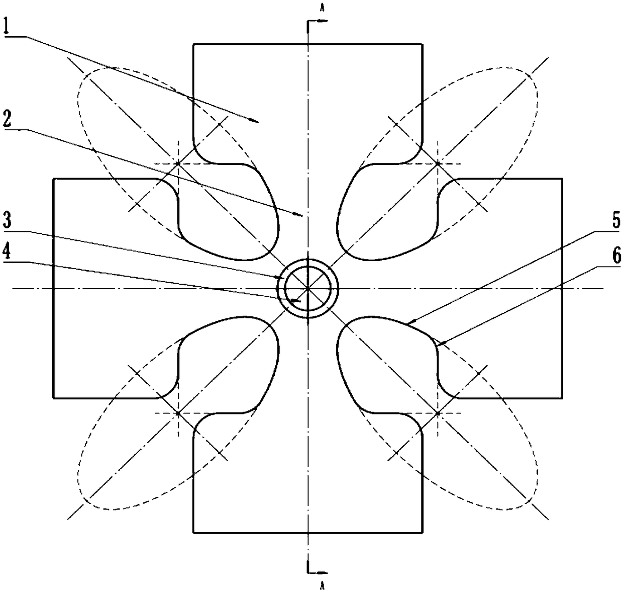
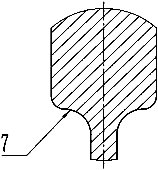
[0029] Such as Figure 1a As shown, a biaxial tensile fatigue test piece with a conic curve transition, the test piece is in the shape of a cross as a whole, with four loading arms, one end of the four loading arms converges into a central area 4, and the other end is a clamping area 1 , the test piece is clamped by means of clamps, etc., and a transition zone 2 formed by a conic curve 5 is provided between the roots of adjacent loading arms. The conic curve 5 is an ellipse, and the major axis of the ellipse coincides with a symmetrical axis of the test piece. The transition between the conic curve 5 and the clamping area 1 is a rounded part 6; the thickness of the clamping area 1 is thicker than that of the central area 4, and there is a thickness reduction area 3 between the transition area 2 and the central area 4; the thickness reduction area 3 Used to connect the thicker transition zone 2 and the thinner central zone 4, the cross-sectional view along the A-A direction is a...

Embodiment 2

[0036] The basic structure of the test piece is the same as that of Example 1, except that the transition mode of the thickness reduction zone 3 in the thickness direction is changed to a spline curve 8, such as figure 2 As shown, where the spline curve 8 satisfies a smooth transition at the connection between the central area 4 and the transition area 2 .

Embodiment 3

[0038] The basic structure of the test piece is the same as that of Example 1, except that the transition mode of the thickness reduction zone 3 in the thickness direction is changed to a single arc 9, such as image 3 As shown, the single circular arc 9 satisfies a smooth transition at the connecting central area 4 .


PUM


Abstract

The invention discloses a biaxial tensile fatigue test piece with conic curve transition and a test method thereof. The whole test piece is in a cross shape and is provided with four loading arms; theends of the four loading arms are integrated into a central area, the other ends of the four loading arms are integrated into a clamping area, a transition area formed by a conic curve is arranged between roots of every two adjacent loading arms, the axis of symmetry of the conical curves at least coincides with one axis of symmetry of the test piece, and a thickness reducing area is arranged between the transition area and the central area and thinned by adopting double arcs or a spline curve or a single arc. The test piece has the advantages that by adopting a conic curve transition mode, the stress strain in the central area is more uniform, and the influence between every two adjacent loading arms is reduced as much as possible; through the design of smooth transition and central areathinning, breakage and cracking of the test piece in the test process occur in the central area at first.

Description

technical field [0001] The invention relates to a tensile fatigue test piece, in particular to a conic curve transition biaxial tensile fatigue test piece and a test method thereof. Background technique [0002] The traditional uniaxial tensile testing method cannot truly reflect the stress of materials in actual engineering. At the same time, many materials have obvious anisotropy, and mechanical testing experiments under biaxial stress can obtain accurate mechanical properties of materials. Therefore, the design of the test piece is particularly important. At present, the biaxial loading experiments on materials mainly include the film swelling biaxial tensile test method, the pressure vessel biaxial tensile test method and the cross-shaped specimen biaxial tensile test method. [0003] In the existing methods, the film swelling method is only applicable to the film member, and the bulging apex is a bidirectional 1:1 stress state; the pressure vessel method is 2:1 for the...

Claims


Application Information

Patent Timeline
IPC IPC(8): G01N3/32
Inventor 费庆国柳友志张大海何顶顶徐文鹏
Owner SOUTHEAST UNIV
Learn More